Objective
Give engineers and procurement teams across the UK and Europe a clear, technically grounded look at how LED PCB assembly actually works, so they can spec boards correctly the first time and avoid the thermal failures that plague badly built LED products.
Key Takeaways
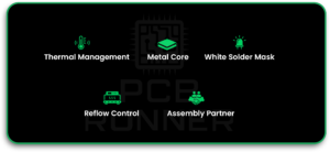
LED PCB assembly depends on getting thermal management right before component placement even begins
Metal core boards (MCPCB) outperform standard FR-4 for anything above a few watts per LED
The white solder mask matters more than most designers realise, and it directly affects lumen output
Reflow profiles for LED assembly need tighter control than standard SMT work
Choosing the right LED PCB Assembly Partner early saves rework later
A customer once sent us a “finished” LED strip design where the LEDs had already started yellowing after three weeks of use. The layout was fine. The components were legitimate. The problem was the substrate: standard FR-4, no metal core, no thought given to where the heat would actually go. That board never had a chance.
This happens more than it should. Teams design the circuit, pick the LEDs, and treat the board itself as an afterthought. But with LEDs, the board isn’t just a mounting surface, it’s the thermal path. Get that wrong and the light output drops, the colour shifts, and the LEDs die early, regardless of how good the driver circuit is.
LED PCB assembly requires managing heat first and populating components second. Metal core substrates, thin prepreg, and stable white solder mask make the difference between an LED board that lasts years and one that dims within months. The right materials and a controlled reflow process matter more here than in standard SMT assembly.
What Is an LED PCB Assembly?
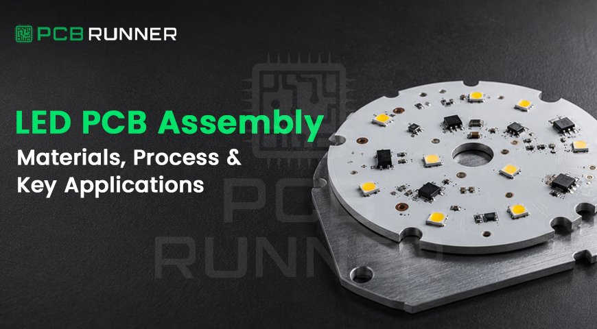
LED PCB assembly is the process of populating a circuit board designed specifically to run and cool LEDs. It covers everything from choosing the substrate to soldering the LEDs and drivers onto it.
It differs from general PCB assembly in one key way: heat dissipation drives every material and process decision. A standard FR-4 board traps heat. An LED board has to move it out.
Component placement is the easy part of LED PCB Assembly. Thermal engineering is where boards succeed or fail, and it’s where most cost-cutting decisions come back to bite a project months later.
LED PCB Materials That Actually Matter
Most LED PCB failures trace back to material choices made before assembly even starts.
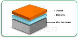
Metal core (MCPCB). For anything running above a couple of watts per LED, aluminium or copper-core boards are the standard. The metal layer pulls heat away from the LED junction and out through the base, instead of letting it build up in the copper traces.
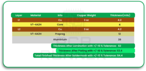
Prepreg thickness. The dielectric layer between the copper circuit and the metal base needs to be thin enough to transfer heat efficiently, but thick enough to insulate properly. Get the bonding wrong and you end up with air gaps. Air gaps act like thermal blankets, trapping heat exactly where you don’t want it.
White solder mask. This one gets overlooked constantly. LEDs throw light in every direction, not just forward. A reflective white mask bounces the side and rear spill back toward the front, boosting usable lumen output. Cheap masks go dull and yellow with heat cycling. A stable mask, made from a material like Taiyo’s LEW1, holds its reflectivity through repeated reflow and years of thermal cycling.
Substrate suppliers. Not all metal core stock performs the same. Boards built on substrates from Bergquist, Arlon, or Thermagon behave predictably under thermal load, which matters when you’re running a production line in the UK or Europe, not a one-off prototype.
This is where LED PCB Materials selection separates boards that last from boards that don’t. For a deeper technical breakdown of layout and thermal design, see our LED PCB design guide.
The LED PCB Assembly Process, Step by Step
1. Substrate Preparation
The metal core gets cut, drilled, and cleaned. Prepreg bonding happens here, with strict control to avoid the air bubbles mentioned earlier.
2. Solder Mask Application
The white reflective mask goes down and cures. This step gets more attention on LED boards than on standard PCBs, since mask quality directly affects finished light output.
3. Solder Paste Printing
Paste is applied through a stencil at the pad locations for LEDs, drivers, and passive components. Paste volume needs tighter control around LED pads than typical SMT pads, since these components are more sensitive to solder voids.
4. Component Placement
LEDs, drivers, resistors, and capacitors get placed by pick-and-place machines. Placement accuracy matters more here. An LED shifted even slightly can cause uneven light distribution across an array.
5. Reflow Soldering
This is where LED PCB Assembly diverges most from standard assembly. Reflow profiles need lower peak temperatures and tighter time-above-liquidus windows to avoid damaging LED phosphor coatings or delaminating the metal core bond.
6. Inspection and Testing
AOI (automated optical inspection) catches placement and solder defects. Functional testing confirms the LEDs actually light up correctly, at the right colour temperature and brightness, before the board ships.
Common Applications
LED boards show up in more places than people expect once they start looking:
- General lighting – downlights, troffers, and linear fixtures for commercial and residential use across the UK and Europe
- Automotive – headlights, tail lights, and interior cabin lighting, where thermal cycling is extreme
- Signage and displays – large-format LED walls and channel letters that run for years unattended
- Medical equipment – surgical lighting and diagnostic devices where colour accuracy is non-negotiable
- Industrial equipment – indicator panels and high-bay lighting in facilities that never fully cool down
Each of these applications puts different demands on the thermal design. A car headlight cycles through extreme heat and cold daily. A commercial downlight runs continuously in a fairly stable environment. The board design should reflect that difference, not use a one-size-fits-all substrate.
What to Look for in an LED PCB Assembly Partner
Not every PCB shop handles LED work well. A few things worth checking before you commit a project:
- Material transparency. Ask which metal core substrate and solder mask they actually use, not just “aluminium” or “white mask” as generic terms.
- Reflow profile control. LED components are sensitive. A shop running one standard profile for every job is a red flag.
- In-house manufacturing. Brokers who outsource fabrication add a layer you can’t verify. Working with a manufacturer that owns its facility means someone can actually answer questions about your specific board.
- Engineering file review. A partner who reviews your Gerbers and BOM before quoting catches problems before they become expensive.
- Component sourcing support. LED and driver components go obsolete fast. A partner who can source hard-to-find parts saves a redesign down the line.
At PCB Runner, we review every engineering file before quoting, at no charge, and we manufacture in our own UK facility rather than brokering the work out. That review step alone catches most of the thermal and material mismatches before they turn into a bad batch.
Cost Factors
LED PCB assembly costs more than standard FR-4 assembly, and the reasons are straightforward:
| Cost Driver | Why It Adds Cost |
| Metal core substrate | Aluminium and copper core material costs more than standard FR-4 |
| Reflective white mask | Premium mask materials (like Taiyo LEW1) cost more than standard green or black masks |
| Tighter reflow control | Slower, more controlled profiles reduce throughput per line |
| Component sensitivity | LEDs and drivers often need handling precautions that add labour time |
| Volume | Small prototype runs cost more per unit than production volumes |
The upside: getting the materials and process right the first time avoids field failures, which cost far more than the incremental material spend.
| Board Type | Typical Use Case | Relative Cost |
| Standard FR-4 LED board | Low-power indicator LEDs | Lowest |
| Single-layer MCPCB | General lighting, signage | Moderate |
| Multi-layer MCPCB | Automotive, high-density arrays | Higher |
| Rigid-flex LED board | Curved or space-constrained fixtures | Highest |
Conclusion
LED PCB assembly rewards attention to material choices most teams skip past. Get the metal core, prepreg, and solder mask right, control the reflow profile, and the board will outlast the fixture it sits in.
If you’re specing a new LED product, contact PCB Runner for a free engineering file review before you commit to a run. It’s the fastest way to catch a thermal problem before it becomes a field failure. Call +44 203 2397011 or email sales@pcbrunner.com to talk through your project.
FAQs
Q. Do I need a metal core board for every LED project, or just high-power ones?
Not always. Low-power indicator LEDs running under half a watt can sometimes get by on standard FR-4 with good thermal relief pours. Once you’re above a watt or two per LED, or running dense arrays, a metal core stops being optional.
Q. Why did my LEDs start dimming after a few months, even though the circuit design was solid?
That’s almost always a thermal issue traced back to the board, not the circuit. Check the substrate, the prepreg bonding, and whether the solder mask has degraded. A yellowing mask is often the visible clue.
Q. Can you assemble LED boards with components I’ve already sourced?
Yes, if you supply a full BOM and the parts are compatible with the board design. We also handle procurement directly, including hard-to-source or obsolete LED and driver parts.
Q. What’s the minimum order quantity for LED PCB assembly?
There’s no fixed MOQ for turnkey LED boards. We can run small prototype batches on an array panel or move straight into production quantities, depending on what the project needs.
Q. How long does an LED PCB assembly project typically take?
Turnaround depends on fabrication and assembly complexity. Quick-turn assembly can run as fast as 3 working days, with fabrication adding another 3 to 4 days on top, depending on the board.