Use SMT for most of your board and keep through-hole for the parts that get pulled, plugged in or run hot. A wrong split is an expensive way to learn the difference.
The SMT vs through hole debate looks settled, but the test data says otherwise. In NASA–DoD combined thermal-cycling and vibration testing, plated-through-hole components proved more reliable overall than surface mount parts. The same project found that component type had a bigger effect on solder joint life than the solder alloy.
That doesn’t mean you should drill holes everywhere. It means the right answer depends on the part, the load it carries and the board around it.
Key Takeaways
- SMT wins on board area, density and automation. Parts sit on surface pads, and machines place and solder them in bulk.
- Through-hole wins on mechanical anchoring, power handling and easy hand rework. Leads pass through plated holes and tie the part to the board.
- Mixed assemblies are the norm. Most modern boards use SMT for the bulk of the parts and through-hole for connectors, transformers and large capacitors.
- Package type matters more than the label. NASA–DoD data shows some surface mount packages survive well and others fail fast.
- Hidden joints change your inspection plan. BGAs and QFNs need X-ray, not just a camera.
SMT vs Through-Hole: How Are the Components Mounted?
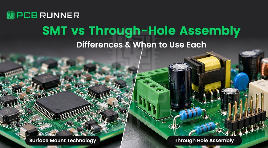
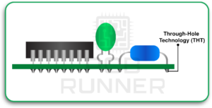
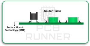
Through-hole components have leads that pass through drilled, plated holes and are soldered on the opposite side of the board. Surface mount technology places components directly onto copper pads on the board surface. Solder paste holds each part in place until reflow. One anchors the part through the board, while the other relies on the surface joint.
Through-Hole Mounting (THT)
Through-hole parts come as axial leads (one at each end) or radial leads (both on one side). The lead runs through the board, so the joint is anchored through the full thickness of the laminate.
That anchoring is why connectors that get mated often, heavy transformers and large capacitors usually stay through-hole.
Surface Mount Technology (SMT) Mounting
SMT parts range from tiny chip resistors to leaded packages and leadless packages like QFNs. They also include BGAs, where an array of solder balls sits under the package.
The upside is size and density. The downside is that the joint sits on the board surface and nothing runs through the board to share the load.
How Do SMT Assembly and Through-Hole Assembly Differ in Process?
SMT assembly prints solder paste through a stencil, places parts with a machine and melts the paste in a reflow oven. Through-hole assembly inserts leads into holes, then solders them with a wave, a selective nozzle or by hand. SMT is built around automation, while through-hole adds separate insertion and soldering steps.
SMT Assembly Steps
- Print solder paste through a stencil onto the pads.
- Inspect the paste for volume and alignment.
- Place components with a pick-and-place machine.
- Reflow the board through an oven so the paste melts and forms joints.
- Inspect the joints with AOI, and X-ray where joints are hidden.
Step one matters most. A chapter on surface-mount technology by Illés, Krammer and Géczy reports that as much as 60–70% of soldering failures trace back to stencil printing. Fix the print and you fix most of the problem.
Through-Hole Assembly Steps
Through-hole PCB assembly follows a different path:
- Insert the leads by hand or with an insertion machine.
- Apply flux and preheat the board.
- Solder by wave, selective soldering or hand soldering.
- Trim leads and inspect the joints on both sides.
The Budapest University of Technology and Economics course notes on through-hole assembly describe how double-wave soldering works. The first, turbulent wave pushes solder into the narrow plated holes. The second, smooth wave removes excess solder and clears bridges.
How Do the Two Methods Affect PCB Design and Board Area?
Surface mount parts need pads on the surface only, so you can populate both sides and leave inner layers free for routing. Through-hole parts need plated holes that cut through every layer, which uses more area and blocks routing. For compact PCB design, SMT almost always wins on space.
Our PCB design guide goes deeper on layout rules, but here’s what changes when you pick one technology over the other.
Board Area and Routing
- Through-hole: every hole removes copper space on every layer. Dense routing gets harder around large pin fields.
- SMT: pads stay on the surface, and vias handle layer changes. You can place parts on both sides.
- Result: the same circuit is usually smaller in SMT, often by a wide margin.
Land Patterns, Stencils and Fiducials
SMT layouts depend on accurate land patterns. IPC-7351 is the standard reference for surface mount land pattern design. Stencil aperture design, pad size and fiducial marks for machine vision all affect yield.
Through-hole layouts depend on hole size, annular ring and spacing for the solder process you plan to use. If a board goes over a wave, part orientation and spacing matter.
Which Components Belong to Each Technology?
Through-hole mounting is often selected for components requiring additional mechanical support, such as frequently mated connectors and certain large or heavy components. However, high-current and high-power applications can use either SMT or through-hole technology. Selection depends on component ratings, PCB copper design, thermal management, mechanical loading and manufacturing requirements.
| Component Type | Usually SMT | Usually Through-Hole |
| Resistors and Capacitors | Chip sizes, ceramic and tantalum | Large electrolytic, film and power types |
| ICs | QFP, QFN, BGA, SOIC | DIP, sockets for socketed ICs |
| Connectors | Small signal and board-to-board | USB, power, terminal blocks, heavy headers |
| Power Parts | Small MOSFETs, diodes | Transformers, relays, TO-220 devices |
| Switches and Controls | Tactile switches | Rotary switches, potentiometers |
Check your bill of materials before you commit to a plan. Some modern ICs are offered only as surface mount packages, so the choice isn’t always yours.
How Do Soldering, Inspection and Testing Differ?
SMT uses reflow soldering, where paste melts in an oven. Through-hole uses wave, selective or hand soldering. Through-hole joints are visible and easy to check. SMT joints need automated optical inspection, and hidden joints under BGAs and QFNs need X-ray.
Soldering Methods
- Reflow (SMT): solder paste melts in a controlled thermal profile. In the NASA–DoD project, the lead-free SAC305 profile targeted a 243 °C peak, and the tin-lead profile used a 225 °C joint peak.
- Wave soldering (THT): the underside of the board passes over molten solder. It’s fast for many through-hole joints.
- Selective soldering (THT on mixed boards): a small nozzle solders specific leads without exposing nearby SMT parts to a full wave.
- Pin-in-paste (THT by reflow): through-hole leads go into paste-filled holes and solder in the same reflow pass as the SMT parts.
Stay alert to temperature limits. Every part on the board must survive the profile you choose.
Inspection and Testing
- Through-hole: joints show on both sides. A trained eye or camera can judge fill and fillet.
- SMT, visible joints: AOI catches missing parts, wrong polarity, shifts and visible solder defects.
- SMT, hidden joints: BGA joints as hidden from normal visual inspection, which is why real-time X-ray is used.
- Acceptance standards: the NASA–DoD test boards were inspected by X-ray and visually against J-STD-001 and IPC-A-610.
Plan test points early. Dense SMT boards leave less room for probes.
Rework Differences
Hand rework on through-hole joints is quick with basic tools. SMT rework needs hot-air or dedicated stations. The NASA–DoD results also showed that reworked components were generally less reliable than unreworked ones, especially reworked lead-free BGA and chip-scale parts.
When Should You Choose Through-Hole?
Choose through-hole when a part faces mechanical stress, high current or heat that a surface joint can’t carry alone. That includes frequently mated connectors, transformers, large capacitors and power parts. It also suits hand-soldered prototypes and very small runs where SMT line setup costs more than it saves.
- Mechanical stress: connectors that get plugged and unplugged, switches and jacks take real force.
- Power and heat: heavy leads and large pads carry more current than most small SMT joints.
- Prototyping: you can swap parts with a soldering iron and no special equipment.
- Test and rework access: through-hole joints are easy to see and touch.
When Should You Choose SMT?
Choose SMT when you need a small board, high component density, short signal paths or automated production at volume. Machines place the parts and one reflow pass solders them, so cost per joint drops as quantities rise. Many modern ICs, including BGAs and QFNs, come only in surface mount packages.
- Miniaturisation: surface pads let you use smaller parts and populate both sides.
- Automation: pick-and-place and reflow handle placement and soldering in bulk.
- Electrical performance: shorter terminations suit fast signals.
- Part availability: many new devices are surface mount only.
Three problems catch teams out:
- Paste printing: this is where most reflow defects start.
- Hidden joints: BGAs and QFNs need X-ray.
- Moisture-sensitive parts: IPC/JEDEC J-STD-020 classifies them, and J-STD-033 covers handling and baking. Skip this and parts can crack during reflow.
What Does the NASA–DoD Data Say About Reliability?
Don’t read “through-hole is stronger” as a rule. In the NASA–DoD overview, the plated-through-hole components were more reliable than the surface mount components in combined testing. Even so, QFN-20 and TQFP-144 surface mount packages were among the best performers, and BGA-225 performed worst.
The shock tests make the point sharper. 53–73% of manufactured DIP-20 through-hole parts failed, against 94–96% of BGA-225 parts and 0–10% of QFN-20 parts.
The lesson is that lead style, package size and board layout all matter. The mounting method is only one factor.
When Is a Mixed SMT/THT Assembly the Right Call?
Mixed assembly fits when most parts are small and dense, but a few need mechanical strength or power handling. Place and reflow the SMT parts first, then insert the through-hole parts and solder them by selective soldering, wave or pin-in-paste. It’s the standard approach for boards that carry connectors.
The SMT vs THT question rarely has a pure answer. A typical sensor or controller board has an MCU, passives and a regulator in SMT, plus a power connector and a transformer in through-hole.
Three Ways to Solder the Through-Hole Parts
- Wave soldering: works, but SMT parts on the underside need protection.
- Selective soldering: targets specific leads without exposing SMT parts to a full wave.
- Pin-in-paste: the stencil must deposit enough paste to fill the hole, and the parts must tolerate reflow temperatures. NASA’s workmanship guidance describes solder performs as a way to add solder for reflow of plated-through-hole components.
Example: A Mixed-Technology Controller Board
This is an illustrative scenario, not a client project.
| Part | Choice | Why |
| Microcontroller (QFN) | SMT | Dense, available only as surface mount |
| Resistors and Capacitors | SMT | Small, machine-placed |
| 5 V Regulator | SMT | Low power, fits a surface pad |
| Power Input Connector | Through-hole | Gets plugged and pulled, needs strength |
| Transformer | Through-hole | Heavy, high-power |
| Electrolytic Capacitor | Through-hole | Large body, leads through the board give a firm anchor |
Quick Decision Guide
| Your Requirement | Lean Toward | Why |
| Small board, high density | SMT | Surface pads, two-sided placement |
| High-volume production | SMT | Automated placement and reflow |
| Frequent mating or pulling | Through-hole | Stronger mechanical anchor |
| High current or heavy parts | Through-hole | Larger leads and pads |
| Hand-built prototype | Through-hole | Simple tools, easy rework |
| Dense board with a few heavy parts | Mixed | Best of both |
Get the Split Right Before You Order
Not sure which parts should be SMT and which should stay through-hole? Talk to the PCBRunner team about your PCB assembly plan, including your BOM, volumes and any parts that take mechanical stress, before you lock the layout.
FAQs
Q. What Is the Main Difference Between SMT and Through-Hole?
SMT parts sit on surface pads and are soldered by reflow. Through-hole parts have leads that pass through drilled holes and are soldered on the other side. SMT is smaller and faster to automate, while through-hole anchors parts more firmly.
Q. Is SMT Better Than Through-Hole?
Neither is better in every case. SMT wins on density and automation. Through-hole wins on mechanical anchoring and power handling. Most boards use SMT for most parts and through-hole for connectors and heavy components.
Q. Can You Use SMT and Through-Hole on the Same PCB?
Yes. Mixed assemblies are common. Fabricators place and reflow SMT parts first, then solder the through-hole parts by wave, selective soldering or pin-in-paste. Plan the layout around the solder method you choose.
Q. Why Is Through-Hole Still Used?
Through-hole leads anchor parts through the board, so they handle mating forces, heavy weight and high current better than most surface joints. They’re also easier to hand-solder, which helps prototyping and repair.
Q. Is SMT Assembly Cheaper Than Through-Hole Assembly?
At volume, usually yes. Machines place parts and reflow solders them together, which cuts cost per joint. For very small runs or boards with few parts, setup costs and part choice can change the answer.
Conclusion
Pick SMT for size, density and automation. Keep through-hole for strength, power and parts that take a beating. For most real boards, the answer is both. Start by sorting your BOM into parts that must survive force or heat and parts that don’t, then build the layout around that split.
Ready to put that split into practice? Send your BOM, volumes and layout files to the PCB Runner team and talk through your PCB assembly options, from SMT Assembly to mixed SMT/THT builds, before you finalise your design.