Key Takeaways
- FR-4 PCB material is a family of flame-retardant glass-epoxy laminates, not one fixed product. Two boards labelled “FR-4” can differ in Tg, loss and expansion.
- Standard FR-4 suits most digital, power and general-purpose boards. It becomes a risk when signal loss, impedance tolerance or assembly temperature drives the design.
- Change the Tg and Td grade first for assembly and via reliability. Move to low-loss epoxy or another laminate family only when a loss budget shows you need to.
- Specify by IPC-4101 slash sheet, not by the words “FR-4” alone.
What is FR-4 PCB material?
It is a woven glass-fabric and epoxy laminate that meets a flame-retardant grade, and it is the default base for most rigid boards. It is good enough for many designs, but the numbers are looser than most people assume. An IPC technical paper on choosing between FR-4 and high-frequency laminates puts typical FR-4 dissipation factor at about 0.020 and notes that the dielectric constant of most FR-4 laminates can vary by ±10% or more.
That spread is why “FR-4” is not a specification. The rest of this guide covers what the datasheet values mean, where standard FR-4 runs out of margin, and what to write on the fabrication drawing.
Is FR-4 One Material, or a Family?
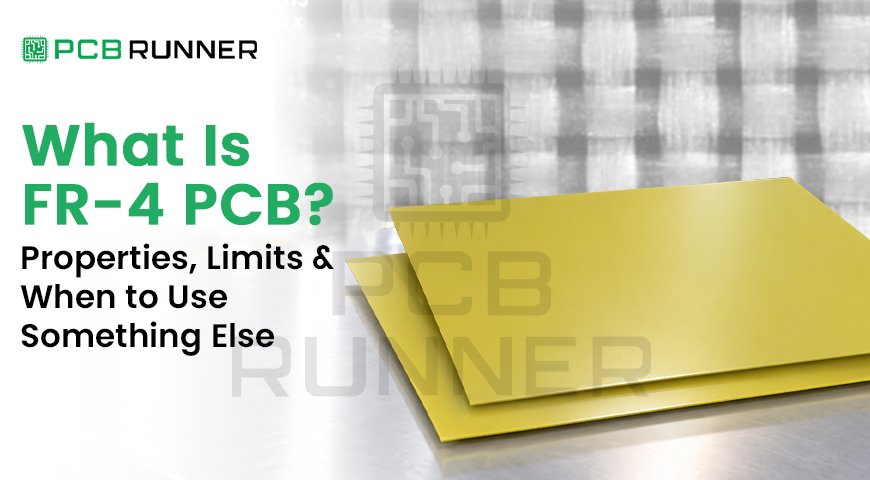
FR-4 PCB material is a family of laminates made from woven E-glass cloth and epoxy resin that typically meet the UL 94 V-0 flame rating. “FR” means flame retardant and “4” is the grade. Each supplier tunes the resin, filler and glass style, so FR-4 is a class of materials, not a single formula.
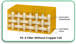
The construction has four parts:
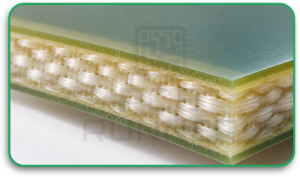
Glass fabric: woven E-glass gives the laminate stiffness and dimensional stability.
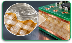
Epoxy resin: the resin binds the glass and sets most of the thermal behaviour, including Tg.
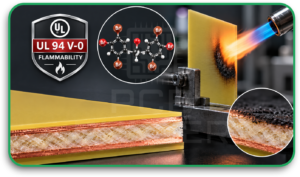
Flame retardant: usually a brominated epoxy. An IPC technical resource on IPC-4101B notes that bound brominated compounds such as TBBPA are acceptable under RoHS. Halogen-free grades also exist.
Fillers: IPC-4101 keeps separate specification sheets for filled and unfilled grades. Filler is mainly used to reduce thermal expansion.
The role of FR-4 in PCB construction is to act as the insulating, structural core between copper layers, and as the prepreg that bonds those layers together. Because resin, filler and glass style differ between suppliers, the datasheet matters more than the label.
FR-4 PCB Properties: What to Check on a Datasheet
The FR-4 PCB properties that decide suitability are dielectric constant (Dk), dissipation factor (Df), glass transition temperature (Tg), decomposition temperature (Td), z-axis expansion and time to delamination (T260, T288). Each one measures a different risk, so check all of them against your board.
Dk and Df: How the Laminate Behaves Electrically
Dk sets signal speed and impedance. Df sets how much signal energy the dielectric absorbs. Typical FR-4 has a Df near 0.020, compared with 0.004 or less for many hydrocarbon high-frequency laminates, according to the same IPC paper. That paper uses 4.2 for a high-performance FR-4 and about 4.5 as a general FR-4 reference.
FR-4 dielectric properties vary with frequency, temperature, resin composition and glass reinforcement. Dk generally changes with frequency, while Df may increase over certain frequency ranges depending on the laminate formulation. For high-speed and RF designs, engineers should use frequency-specific Dk and Df values from the selected laminate manufacturer’s datasheet.
Temperature matters too. A recent IEEE study of an FR-4 laminate estimated a 9% drop in real permittivity and a 70% drop in loss tangent between 300 K and 4 K. NIST measurements found loss tangent generally increased with temperature in an organic substrate. Use the Dk and Df your laminate maker publishes at your operating frequency, not a generic 4.5.
Tg and Td: The Thermal Limits
Tg is the temperature at which the resin shifts from a rigid, glassy state to a softer, rubbery one. Expansion accelerates above it. Tg is a transition point, not a maximum operating temperature.
Td is the temperature at which the laminate loses 5% of its mass in thermogravimetric analysis (IPC-TM-650 2.4.24.6). Lead-free FR-4 sheets in IPC-4101B set Td minimums between 310 °C and 340 °C, which leaves margin above typical lead-free reflow peaks.
Z-Axis Expansion, T260 and T288: Via Reliability
Z-axis expansion is how much the board grows in thickness when heated. IPC-4101B limits it to 60 ppm/°C below Tg and 300 ppm/°C above Tg on its lead-free FR-4 sheets, plus a total expansion cap between 50 °C and 260 °C.
T260 and T288 are the minutes a laminate survives at 260 °C or 288 °C before delaminating. Longer times matter for boards that see several reflow passes or rework.
Which FR-4 Grade Do You Need? Standard, Mid-Tg or High-Tg (IPC-4101 table)
Select an FR-4 grade based on the assembly thermal profile, board thickness, layer count, operating conditions and reliability requirements. Standard-Tg FR-4 may be suitable for lead-free assembly when its thermal properties meet the process requirements. Higher-Tg grades may offer additional thermal margin, but Tg alone does not determine suitability. Td, z-axis expansion and T260/T288 performance should also be evaluated.
| IPC-4101B Sheet | Tg Min | Td Min | Z-Axis Expansion, 50–260 °C | T288 | Typical FR-4 PCB Applications |
| /101 (filled), /121 (unfilled) | 110 °C | 310 °C | 4.0% max | 5 min | Consumer electronics, simple controllers, low-power I/O boards |
| /99 (filled), /124 (unfilled) | 150 °C | 325 °C | 3.5% max | 5 min | Multilayer industrial controls, moderately thick boards |
| /126 (filled), /129 (unfilled) | 170 °C | 340 °C | 3.0% max | 15 min | Automotive, power conversion, servers, multi-reflow assemblies |
Values are from the IPC summary of IPC-4101B. IPC calls the 150 °C sheets “high Tg” and the 170 °C sheets “very high Tg”, while many datasheets call 150 °C “mid-Tg”. Application examples are typical use, not IPC requirements. Confirm values against the revision your drawing cites.
At What Frequency Does FR-4 Stop Being Suitable?
No single frequency or data rate ends FR-4’s usefulness. It stops being suitable when dielectric loss over your trace length uses up the channel’s loss budget, or when Dk and thickness variation push impedance outside tolerance. Because FR-4’s Df rises with frequency, margin shrinks as speed and length increase.
Why FR-4 Causes Signal Loss and Impedance Variation
Several factors combine:
- Loss: a Df near 0.020 absorbs far more energy than the 0.004-or-lower values of many hydrocarbon laminates.
- Dk tolerance: the Dk of most FR-4 laminates can vary ±10% or more, while many high-frequency laminates hold ±2% or better.
- Thickness tolerance: many FR-4 laminates carry ±15% thickness tolerance or more, against about ±7% for typical high-frequency laminates. Dielectric height directly sets impedance.
- Temperature drift: the IPC paper notes that most FR-4 laminates have a relatively high thermal coefficient of Dk, so impedance shifts as the board warms.
- Glass weave and copper roughness: glass bundles and resin gaps differ in Dk, so a trace sees local variation along its length. Rough copper adds loss at high frequency.
Impedance targets have also tightened. The IPC paper notes that ±10% is now standard, and many designs ask for ±7% or ±5%.
To decide, run a channel simulation at your highest frequency using the datasheet Dk and Df. If the loss budget fails, work through the options in order: smoother copper and spread-glass styles, then low-loss epoxy laminates (see IPC-4103 for high-speed and high-frequency base materials), then hydrocarbon or PTFE laminates.
What Causes Delamination and Barrel Cracking in FR-4 Boards?
Delamination and barrel cracking come from thermal stress exceeding what the laminate and the copper barrel can tolerate. The usual causes are z-axis expansion above Tg, absorbed moisture, repeated reflow or rework, and a Td or T288 rating too low for the assembly process.
The mismatch is large. A patent record published by the European Patent Office states that between 30 °C and 270 °C, conventional glass-epoxy laminates expand about 5% along the z-axis while the copper in a plated-through hole expands only 0.4%. The IPC paper adds that a z-axis CTE of about 50 ppm/°C or less is generally considered acceptable for good plated-through-hole reliability in high-performance FR-4.
To prevent failures:
- Choose a sheet with a Td and T288 that cover your reflow profile with margin.
- Use filled, lower-expansion grades for thick boards and high layer counts.
- Bake boards before assembly if they have been exposed to humidity. The IPC paper notes most FR-4 laminates absorb a moderate amount of moisture.
- Ask your fabricator about via aspect ratio and copper plating ductility.
- Tell the fabricator how many reflow and rework cycles to expect.
When to Use Something Other Than FR-4
Switch when the loss budget, impedance tolerance, humidity exposure or temperature exceeds what epoxy-glass can deliver. Hydrocarbon laminates suit RF and many high-speed designs, PTFE suits the lowest-loss work, and polyimide suits heat. Each step costs more and demands closer process control.
| Material | Typical Df | Strengths | Fabrication Notes |
| Standard FR-4 | ~0.020 | Low cost, well-defined processing | Dk ±10% or more; moisture uptake |
| Thermoset Hydrocarbon (RO4350B-Type) | ≤0.004 | Tight Dk, low moisture, Tg above 280 °C | Processes similarly to FR-4 |
| Ceramic-Filled PTFE | ≤0.002 (many grades) | Very low loss | Usually needs plasma or similar hole preparation |
| Nearly Pure PTFE | ~0.001 or less | Lowest loss | Special drilling and sodium naphthalene hole treatment; high z-axis CTE |
Polyimide laminates address a different problem: heat. The EPO patent record describes high-Tg glass-reinforced polyimide resisting plated-through-hole thermal stress cracking under conditions where glass-epoxy failed. For a deeper material-by-material breakdown, see our guide to Rogers vs PTFE vs FR4.
Can You Mix FR-4 and Rogers in One Stack-Up?
Yes. A common hybrid puts a high-frequency laminate on the critical electrical layers, such as the top microstrip layers, and FR-4 on the remaining layers. The IPC paper says the fabrication is generally not much more complicated with hydrocarbon laminates, and that a hybrid can reduce overall CTE compared with an all-PTFE build.
Hybrids with nearly pure PTFE need more care. The FR-4 holes get plasma or permanganate treatment first, then the PTFE gets sodium naphthalene treatment. FR-4 boards are generally lower cost, but the IPC paper also points out that better impedance yield on tight-tolerance designs can offset part of the laminate premium. Ask your fabricator whether they have run your exact material pair.
How to Specify and Verify FR-4 on a Drawing
Specify the laminate by IPC-4101 slash sheet, with Tg, thickness and copper weight, rather than writing “FR-4”. The slash sheet defines minimum properties and avoids locking you to one brand. Then ask the fabricator for the datasheet and evidence that the delivered laminate matches it.
A fabrication note might read:
Base material: IPC-4101/126, Tg ≥170 °C, Td ≥340 °C. Laminate and prepreg per attached stack-up. Finished copper: 1 oz outer, 0.5 oz inner. Controlled impedance as marked. Equivalent materials acceptable with fabricator approval.
State the IPC-4101 revision on the drawing. IPC publishes IPC-4101 Revision E with Amendment 1, and the IPC standards catalogue lists IPC-4103 separately for high-speed and high-frequency base materials.
How to Verify the Laminate
To verify a laminate:
- Tg: measured by DSC, TMA or DMA on a coupon.
- Td: measured by TGA, per IPC-TM-650 2.4.24.6.
- Dk and Df: use a test at your frequency of interest. IPC-TM-650 2.5.5.9 covers 1 MHz to 1.5 GHz and is not intended for low-loss materials, and IEC 61189-2-721 describes a split-post dielectric resonator method for microwave frequencies. NIST’s guide to dielectric and conductor-loss measurement explains the trade-offs between methods.
- Impedance: confirm with TDR on test coupons built into the panel.
When you ask a UK or EU fabricHow to Verify the Laminateator for a quote, request the laminate datasheet, the frequency at which Dk and Df were measured, the stack-up with the Dk and Df values used for impedance, and lot certification where available. Good PCB design depends on these inputs, because a generic Dk can put every impedance calculation off.
Get the Laminate Decision Right Before Layout
If you are unsure whether standard FR-4, a higher-Tg grade or a low-loss laminate fits your board, send your stack-up, highest frequency, assembly profile and operating temperature to the PCB Runner team for a material review before you release the design.
FAQs
Q. What Does FR-4 Stand For?
“FR” stands for flame retardant, and “4” is the grade designation for woven glass-epoxy laminates. It describes a class of FR4 material, not one formula, so properties vary by supplier and by IPC slash sheet.
Q. Is FR-4 Good for High-Frequency PCBs?
Standard FR-4 works at low frequencies, but its Df near 0.020 rises with frequency and causes growing loss. High-frequency and long-channel designs usually need low-loss epoxy or a hydrocarbon laminate, chosen after a loss-budget simulation.
Q. What Tg Do I Need for Lead-Free Soldering?
Several IPC-4101 sheets are designed for lead-free assembly, with Tg minimums from 110 °C to 170 °C. Choose by Td, T288 and z-axis expansion as well as Tg, especially for thick or multi-reflow boards.
Q. What is the maximum operating temperature of FR-4?
Most FR-4 laminates carry a continuous-use rating (UL relative thermal index) of roughly 105 to 130 °C, though some grades are rated higher. This is separate from Tg, which is only where the resin softens. Short assembly peaks such as lead-free reflow are covered by Td and T260/T288, so check the datasheet for your grade.
Q. Do I Need to Name a Brand on My Fabrication Drawing?
No. Call out the IPC-4101 slash sheet, revision, Tg, thickness and copper weight, and allow approved equivalents. This keeps the requirement clear while letting the fabricator use qualified stock from various FR4 circuit board materials.
Conclusion
Standard FR-4 remains the right PCB material for most boards, but “FR-4” is only a starting point. Match the Tg, Td and T288 grade to your assembly profile first. Move to low-loss or Rogers-type laminates only when a loss-budget simulation or impedance tolerance shows you need them, then write the requirement as an IPC-4101 slash sheet and ask for verified data.