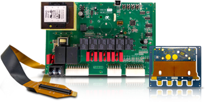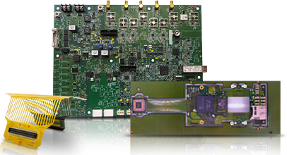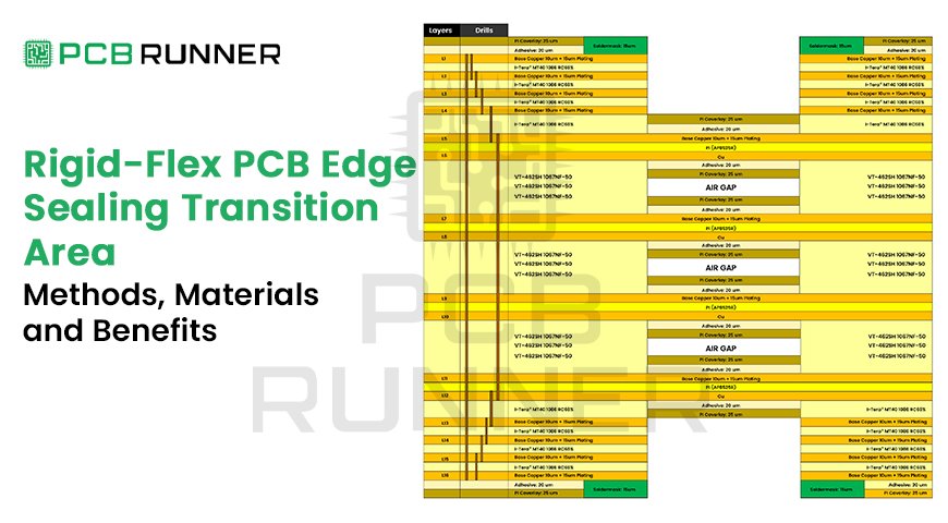
At the rigid-to-flex transition, a flexible sealant or strain-relief fillet may be applied to protect exposed laminate edges and reduce mechanical stress during bending. Depending on the material and application, it can also help limit moisture and contamination ingress. Not every rigid-flex PCB requires this additional protection.
Polyimide and its adhesives can absorb 0.8% to 2.0% moisture, and that water has to go somewhere. On rigid-flex printed circuit boards, the seam between rigid and flex is where contaminants tend to get in and where stress concentrates. This guide explains what edge sealing is, when you need it, which materials and methods fit, and how to put it on your drawing.
Key Takeaways
- Edge sealing protects the rigid-to-flex junction from moisture, flux, cleaning chemicals and contamination.
- It is not the same as coverlay or conformal coating. Each protects a different area.
- The seal must stay flexible and stay out of the dynamic bend zone, or it creates a new stress point.
- Whether you need it depends on the environment, the bend type and the assembly process. No single rule covers every board.
- Give your fabricator the stack-up, environment, bend details and an acceptance check, not just a note saying “seal edges”.
What Is Edge Sealing, and What Does It Protect?
Edge sealing is a bead or coating of flexible sealant applied along the rigid-to-flex junction and any exposed laminate edges beside the flex area. It closes the gap where moisture, flux and cleaning chemicals could enter the board. It also softens the step in thickness between the rigid and flexible sections.
The idea is established. One US patent for rigid/flex board manufacturing describes a flexible sealing coating over the edges of the rigid structure next to the flex area, applied to seal the circuit against moisture and other contaminants.
Where does the seal go?
- Along the rigid edge where the flex exits, on both faces of the board
- Around cut-outs or windows where flex layers are exposed
- Clear of the bend zone, pads and mounting holes, unless your fabricator advises otherwise
A well-built rigid flex PCB already uses coverlay and controlled lamination. The edge seal adds protection at the one place those layers meet a hard edge.
Why and When Do Rigid-Flex Boards Need Edge Sealing?
Edge sealing or strain relief may be specified when the rigid-to-flex transition requires additional environmental or mechanical protection. The need depends on the PCB construction, exposure to moisture or chemicals, bend radius, expected flex cycles and overall product design. A suitable sealant can reduce certain risks, but it does not replace correct lamination, bend design or environmental qualification.
What goes wrong without it?
Failures at this seam tend to come in four forms:
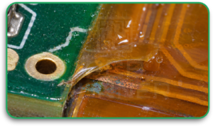
- Coverlay lifting. Coverlay bonds well to polyimide but poorly to FR-4, so the rigid interface can let moisture in and invite corrosion.
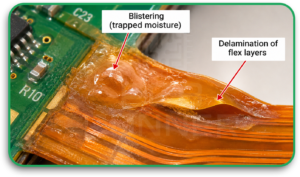
- Trapped moisture. Contaminants that enter the board can cause blistering and delamination of the flex.
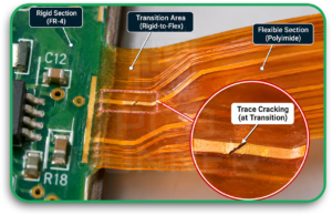
- Trace cracking. Abrupt changes in thickness and stiffness focus strain on copper and coverlay, so the trace can crack at the transition.
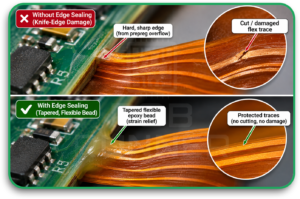
- Knife-edge damage. Overflow from no-flow prepreg can form a hard edge that cuts into flex traces when the board bends. A tapered flexible epoxy bead at the junction softens that transition.
When does a board actually require it?
There is no universal rule. The table below is a practical guide, so confirm it with your fabricator.
| Operating condition | Edge sealing |
| Dry, sealed enclosure, static bend | Often optional |
| High humidity or condensation | Recommended |
| Washdown, sterilisation or harsh cleaning agents | Recommended |
| Fuel, oil or solvent exposure | Recommended |
| Vibration or repeated flexing | Recommended, with a flexible material |
Which Sealing Materials and Methods Work Best?
Fabricators typically use a flexible epoxy or another flexible polymer, applied as a dispensed bead or a thin coating and then cured. The right choice balances moisture and chemical resistance against flexibility. It must also survive your reflow and operating temperatures.
What are the common sealing materials?
These are typical traits only. Your fabricator will confirm which materials it has qualified.
| Material | Strengths | Watch-outs |
| Flexible epoxy | Strong adhesion, good chemical resistance, forms a tapered bead | Must be a flexible grade, since rigid epoxy can crack in service |
| Silicone | Very flexible, tolerant of wide temperature swings | Check adhesion and compatibility with later soldering or coating steps |
| Polyurethane | Good moisture and abrasion resistance | Can be harder to rework |
| Thin polymer coating | Covers edges with minimal added bulk | May give less build-up at a large thickness step |
How does the base rigid-flex PCB material affect sealing?
The rigid-flex PCB material underneath sets the baseline. Polyimide flex cores and their adhesives absorb moisture, so pre-baking before assembly helps prevent bubbles and delamination.
Coverlay adhesion to FR-4 is weaker than to polyimide, which is why the seal sits at that boundary. Your stack-up choices, including coverlay termination and prepreg opening, change how much help the seal needs.
How is the seal applied?
Common routes are a dispensed bead and a masked coating, followed by thermal or UV cure depending on the material. The fabricator controls bead size, placement and cure. That is why it needs to see your design before you finalise the note.
How Is Edge Sealing Different From Coverlay and Conformal Coating?
Coverlay is a polyimide film laminated over flex circuitry during fabrication. Conformal coating is a thin protective film applied over the finished assembly. Edge sealing is a targeted seal on the rigid-to-flex junction and exposed edges. They protect different areas, and many boards use more than one.
| Coverlay | Conformal coating | Edge sealing | |
| What it is | Polyimide film with adhesive | Thin polymer film | Flexible bead or coating |
| When applied | During fabrication | After assembly | During or after fabrication |
| Main job | Insulate and protect flex traces | Protect assembled components and boards | Seal the junction and exposed edges |
| Where | Over flex circuitry | Over the finished board | Rigid-to-flex seam |
Because the seal sits near reflowed areas, check that the material survives your soldering profile. Our Rigid-Flex PCB assembly page covers the build side.
Does Edge Sealing Change Flexibility and Reliability?
Done well, edge sealing improves reliability and leaves flexibility intact. Done badly, it stiffens the bend and moves the stress to a new spot. Keep the seal flexible, tapered and out of the dynamic bend zone, and do not expect it to rescue a weak lamination bond.
Can it prevent delamination?
It reduces one cause, which is moisture and contamination getting into the junction. It cannot fix voids, poor adhesion or the wrong stack-up, so lamination quality still comes first.
What about thicker boards and tight bends?
A thicker rigid section creates a bigger step, and a tighter bend puts more strain near the seam. Ask your fabricator whether the bead profile should change, and keep vias, pads and stiffener edges away from the bend tangent.
How Do You Specify Edge Sealing on a Drawing?
State the location, material class, flexibility limits and acceptance check on your fabrication drawing, then back them up with stack-up and environment details. A vague note such as “seal edges” leaves the fabricator guessing about coverage, material and where the seal must not go.
Here is an illustrative note. It is an example format, not a standard.
Apply a flexible edge seal along the rigid-to-flex boundary on both faces. Material: [flexible epoxy / per fabricator qualification]. Keep the seal clear of the bend zone, pads and mounting holes. The seal must remain flexible after cure and withstand lead-free reflow. Inspect per [agreed criteria].
What does the manufacturer need from you?
- Stack-up and layer count, with rigid, flex and transition boundaries marked
- Bend details: radius, angle, and whether the flex is static or dynamic
- Environment: humidity, chemicals, temperature range and vibration
- Assembly process: reflow profile, cleaning agents and any sterilisation
- Keep-out areas where the seal must not go
- Quality class and acceptance criteria
How Can You Verify Coverage Before Production?
Agree acceptance criteria before the first build, then check the seal on a prototype. Visual inspection confirms coverage and placement, microsectioning shows what is happening inside the junction, and a bend test confirms the seal has not stiffened the flex.
A sensible verification routine looks like this:
- Inspect under magnification against the drawing, looking for gaps, voids and seal creeping onto pads.
- Microsection a sample to see the seal, coverlay and laminate interface.
- Bend-test after sealing to the real radius and cycle count.
- Run environmental checks that match your use, such as humidity or thermal cycling.
IPC-6013 sets qualification and performance requirements for flex and rigid-flex boards, so reference it in your specification.
Can a UK or European Manufacturer Recommend the Right Method?
Yes, a manufacturer that builds rigid-flex boards can advise on seal material and placement, because it knows its own lamination and cure processes. PCB Runner states that its engineering team supports customers from early design to production, and that it reviews engineering files at no charge.
As a Rigid-Flex PCB manufacturer serving the UK and Europe, PCB Runner also lists flex prototyping with no minimum quantity. That gives you a low-risk way to test a seal on a small run. Confirm edge sealing as part of the build when you request your quote.
FAQs
Q. What is the weakest point of a rigid-flex PCB?
The rigid-to-flex transition is often the highest-risk location. Abrupt changes in thickness and stiffness focus strain there, which can lead to trace cracking, coverlay lifting or delamination.
Q. Is edge sealing the same as conformal coating?
No. Conformal coating is a thin film over the finished assembly. Edge sealing is a targeted seal on the rigid-to-flex junction and exposed edges. Some boards use both.
Q. Does edge sealing make a rigid-flex board stiffer?
It can if the material is too hard or the bead reaches the bend zone. Use a flexible material, keep a taper, and keep the seal out of the dynamic bend area.
Q. Can edge sealing stop delamination?
It lowers the risk from moisture and contamination entering the junction. It cannot repair poor lamination, voids or the wrong stack-up.
Q. How do I specify edge sealing to my fabricator?
Give the location, material class, keep-out areas, flexibility requirement and acceptance check. Add your stack-up, bend details, environment and assembly process.
Conclusion
Edge sealing is a small step that protects the most stressed seam on your board. Match the material to your environment, keep the seal flexible and out of the bend, and write a specific note with an acceptance check.
If you are weighing a design, send your stack-up and operating conditions to PCB Runner and ask for engineering input before you finalise the drawing.