Objective:
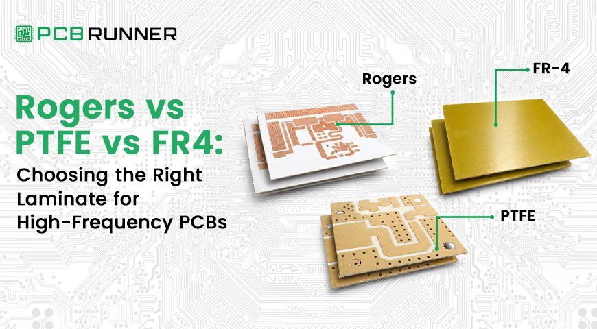
Give RF and hardware engineers a clear, technically grounded way to choose between FR4, Rogers, and PTFE laminates for high-frequency designs, without the marketing fluff most comparison guides lean on.
Key Takeaways
- High frequency PCB material selection comes down to three numbers: dielectric constant (Dk), dissipation factor (Df), and how stable both stay across frequency and temperature. Get those wrong and the board underperforms no matter how clean the layout is.
- Standard FR4 has a Dk of roughly 4.2 to 4.6 and a loss tangent around 0.02. Past 1 GHz, that loss starts degrading signal integrity in ways layout tricks can’t fully fix.
- Rogers laminate PCB materials like RO4003C and RO4350B hold a stable Dk near 3.5 to 3.7 with Df as low as 0.0027, making them the default choice for RF, radar, and 5G designs up to tens of GHz.
- PTFE PCB material goes further still, with Dk as low as 2.2 and the lowest loss of any common substrate, but it costs more and needs specialized processing.
- The right choice isn’t “always use Rogers” or “FR4 is obsolete.” It’s matching frequency, loss budget, and cost tolerance to the material actually built for that job.
A design that works perfectly on FR4 at 500 MHz can fall apart at 5 GHz, and the layout hasn’t changed at all. What changed is that the substrate itself started acting like part of the circuit.
That’s the part most engineers learn the hard way. High frequency PCB material selection isn’t a spec you tick off a datasheet. It’s the decision that determines whether your RF front end hits its noise figure, whether your radar module holds calibration across temperature, and whether your 5G antenna array performs the way simulation said it would.
This guide breaks down FR4, Rogers, and PTFE on the numbers that actually matter, not brand reputation, so you can pick the right laminate the first time instead of finding out in the lab.
What Actually Changes When You Move to High-Frequency PCB Design?
Above roughly 1 GHz, the PCB substrate stops being a passive backing and starts shaping the signal directly. Dielectric constant and dissipation factor determine how fast the signal travels and how much of it gets lost as heat along the way.
Three properties drive this:
- Dielectric constant (Dk): Controls impedance and signal velocity. A shifting Dk across frequency detunes filters and skews differential pairs.
- Dissipation factor (Df): Also called loss tangent. It directly sets insertion loss. Lower Df means more of your signal actually arrives at the far end.
- Thermal stability: Dk and Df both drift with temperature. A material that looks fine on the bench can shift enough in the field to move a filter’s center frequency or detune an antenna.
At frequencies above roughly 20 GHz, copper surface roughness starts contributing meaningfully to loss too, because the signal current crowds into a thin layer near the copper surface (the skin effect). That’s one more reason material choice and copper finish both matter more as frequency climbs.
FR4: When Standard Material Still Works, and When It Doesn’t
Standard FR4 handles most digital and low-frequency analog designs fine, but its dielectric loss climbs fast enough above 1 GHz that RF and microwave circuits need something built for the job.
FR4 is woven fiberglass bonded with epoxy resin. It’s affordable, mechanically strong, and easy to fabricate, which is why it dominates consumer electronics, industrial controls, and general computing hardware.
Its numbers, though, work against it at higher frequencies:
- Dielectric constant: roughly 4.2 to 4.6 at 1 MHz
- Loss tangent: around 0.02
- Standard Tg: 130°C to 150°C, with high-Tg variants reaching 170°C to 180°C
That loss tangent is the problem. At 100 MHz it’s a rounding error. At 5 GHz on a long trace, it’s the difference between a clean signal and one that’s lost half its power before it reaches the receiver.
High-Tg or modified low-Dk FR4 variants (Isola 370HR, FR408HR) push the ceiling higher and work well as a middle ground for designs that need better thermal stability but don’t quite justify a full RF laminate. Still, past a few GHz, they’re a bridge, not a destination.
Rogers Laminates: What Makes Them the RF Industry Standard?
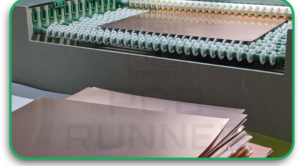
Rogers laminate PCB materials hold a stable, low dielectric constant across frequency and temperature, which is exactly what filters, antennas, and RF amplifiers need to perform predictably. That stability, not brand name, is why Rogers dominates this space.
Rogers Corporation makes several material families, each aimed at a different application:
| Series | Best For | Typical Dk / Df |
| RO4000 (RO4003C, RO4350B) | Power amplifiers, antennas, general RF/microwave | Dk 3.55-3.66, Df 0.0027-0.0037 at 10 GHz |
| RO3000 | Automotive radar, satellite communications | Dk 3.0-3.5 range |
| RO6000 | Military and aerospace systems | Higher-performance, application-specific |
| RT/duroid | High-power and space-grade applications | Dk 2.2-10.2 depending on grade, Df as low as 0.0009 |
RO4003C and RO4350B are the workhorses most engineers reach for first. They process almost like FR4 (no special through-hole treatment required), which keeps fabrication cost and complexity manageable while still delivering RF-grade performance.
RF PCB substrate choice inside the Rogers family usually comes down to how tightly you need Dk controlled and how much power the board has to handle, not just top-line frequency.
PTFE: When Do You Actually Need the Lowest Loss Available?
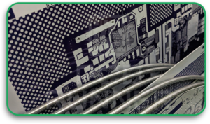
PTFE PCB material delivers the lowest dielectric loss of any common laminate, with Dk as low as 2.2, which makes it the right call for the small set of designs where every fraction of a dB matters.
Often marketed under the RT/duroid name, PTFE is used in several Rogers products as a PTFE-based composite. The material stands out as a top performer for high-frequency applications, particularly when minimizing signal loss is a priority. But it comes with real trade-offs:
- Mechanically soft, which complicates drilling and plating
- Requires specialized processing steps most standard fabricators don’t stock
- Higher material cost than Rogers hydrocarbon-ceramic laminates
- Sourcing and storage windows matter. PTFE stock can take longer to source, and it has a limited shelf life once opened, so confirm availability before committing to a tight schedule
That combination is why PTFE tends to show up in space-grade, military radar, and precision phased-array systems rather than general RF work. If a Rogers hydrocarbon laminate meets your loss budget, it’s almost always the more practical choice.
Rogers vs PTFE vs FR4: Side-by-Side Comparison
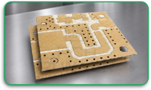
| Property | FR4 | Rogers (RO4000 series) | PTFE |
| Dielectric constant (Dk) | 4.2-4.6 | 3.0-3.7 | As low as 2.2 |
| Loss tangent (Df) | ~0.02 | 0.0027-0.0037 | Lowest available, often under 0.001 |
| Thermal stability | Moderate (Tg 130-180°C) | High, stable across temperature | Very high, but softer mechanically |
| Fabrication complexity | Standard | Near-standard, minor process changes | Specialized, requires experienced processing |
| Typical frequency range | Up to ~1 GHz reliably | Hundreds of MHz to tens of GHz | RF through microwave, highest-performance tier |
| Relative cost | Low | Moderate to high | Highest |
This table is the shortcut version. The right answer still depends on your specific frequency, loss budget, and whether the application can tolerate the cost step-up.
How Do You Actually Choose Between Them?
Match the material to your operating frequency and loss budget first, then check whether cost or manufacturability rules anything out. Frequency alone doesn’t decide it. A short trace at 6 GHz might tolerate FR4; a long one won’t.
A practical way to work through it:
- Establish your operating frequency and trace length. Short interconnects are more forgiving than long runs, even at the same frequency.
- Calculate your loss budget. If FR4’s 0.02 Df pushes your insertion loss past spec, move to a lower-Df material.
- Check thermal requirements. Automotive radar and outdoor RF equipment see wide temperature swings; Rogers and PTFE hold Dk more consistently than FR4 across that range.
- Consider a hybrid stackup. Many designs route RF and microwave signals through a Rogers layer while keeping power and low-frequency layers on standard FR4. This controls cost without compromising the sensitive layers.
- Confirm manufacturability with your fabricator early. Not every shop stocks Rogers or PTFE, and lead times differ. Flag material choice at the RFQ stage so it doesn’t surface as a delay later.
A common real-world pattern: a 5G small-cell antenna board routes the RF front end on RO4350B and the digital control and power sections on standard FR4, bonded together in one stackup. That keeps the expensive material limited to where it actually earns its cost.
What Does High-Frequency Material Selection Cost You?
Rogers and PTFE both cost meaningfully more than FR4, but the real cost driver is how much of the board actually needs to be built from them, not a flat per-board multiplier.
Rough guidance:
- FR4 remains the cost baseline for the entire industry.
- Rogers RO4000 series typically runs several times the cost of FR4 per panel, depending on thickness and copper weight.
- PTFE sits above Rogers, driven by material cost and the specialized handling it needs during drilling and plating.
- A hybrid stackup (Rogers or PTFE only where the RF layers need it) usually lands well below an all-Rogers or all-PTFE board, while still meeting performance targets.
The mistake to avoid is over-specifying. Pulling PTFE into a design that a Rogers hydrocarbon laminate would handle just fine adds cost and lead time without a performance payoff.
Get Your High-Frequency Material Right the First Time
Material selection is the one decision in RF design you can’t route your way around after the fact. Explore PCB Runner’s high-frequency PCB capabilities, check the full material options available, or send over your frequency and loss requirements and we’ll help you land on the right laminate before you commit to a stackup.
FAQs
Is Rogers always better than FR4 for RF designs?
Not always. Below about 1 GHz on short traces, FR4 often performs fine and costs far less. Rogers earns its premium once frequency, trace length, or loss budget push past what FR4’s dissipation factor can support.
Can I mix FR4 and Rogers in the same PCB?
Yes. Hybrid stackups route RF-critical signals through a Rogers layer while power and digital sections stay on FR4. It’s a common way to control cost on boards that only need high-frequency performance in part of the design.
Why does PTFE cost more to manufacture than Rogers?
PTFE is mechanically softer and needs specialized drilling and plating steps that standard FR4 processing doesn’t use. That extra handling, plus the material cost itself, is what pushes the price up.
What frequency range actually needs Rogers instead of high-Tg FR4?
Roughly above 1 to 2 GHz, depending on trace length and loss tolerance. High-Tg FR4 can push a bit higher for less demanding designs, but true RF and microwave work generally needs Rogers-grade Dk stability.
Does PCB Runner stock Rogers and PTFE materials?
Yes. PCB Runner fabricates high-frequency boards in Rogers and PTFE laminates alongside standard FR4, so RF, radar, and 5G designs get the right substrate without a separate sourcing process.