Select the wrong dielectric substrate, and even a perfectly designed PCB will fail, it is that simple.
While finalizing signal integrity through testing, engineers spend weeks perfecting it. However, keeping the substrate and its thickness in consideration is really important. This mismatch comes up when the pcb manufacturer starts their analysis on DFM checks. Studies by IPC show that material-related issues account for a significant share of PCB failures, both in manufacturing and in the field. PCB material selection is not a background decision. It is one of the most important calls you will make in the entire design process.
At PCB Runner, we have catch tens of PCB designs with this issue. Due to which we have prepared this guide covers what you actually need to know, written plainly so that you can make the right call the first time.
Key Takeaways
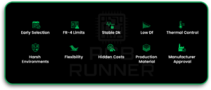
- PCB material selection should be made early as per IPC-4101, IPC-4202, IPC-2222/2223 – not after the layout is finished.
- FR-4 is reliable for many standard products, but it is not suitable for every design.
- High-frequency designs need materials with stable Dk and low Df.
- High-power boards need better thermal conductivity than standard FR-4 can usually provide.
- Selection of PCB substrates must be done considering the environment for where the boards need to perform.
- Flexible and rigid-flex materials are necessary when the product bends or must fit into tight mechanical spaces.
- The cheapest material / Non UL listed materials can become expensive if it causes failures, rework, or warranty issues.
- Material choice should be checked/confirmed with the manufacturer before finalizing the stackup and starting design layout.
- The right PCB material is the one that meets the electrical, thermal, mechanical, cost, and supply needs of the product.
Dielectric substrates are the pillar of PCB. Choose it wisely as you give to every other part of your design.
Why PCB Material Selection Matters More Than You Think
The material is the foundation of every PCB. Every trace, every via, every component sits on top of it, and depends on it.
Impact on Electrical Performance and Signal Integrity
The substrate material controls how fast electrical signals travel and how much they degrade along the way. Two key properties, dielectric constant (Dk) and loss tangent (Df), vary significantly between materials. A higher Dk slows down signals. A higher Df absorbs signal energy and creates loss. For designs running above 1 GHz, these differences are not theoretical. They cause real signal distortion, impedance mismatches, and timing errors that are very hard to fix after fabrication.
Role in Thermal Management and Heat Dissipation
Every PCB generates heat during operation. The material must be able to handle that heat and move it away from sensitive components. Standard FR-4 has a thermal conductivity of around 0.3 W/m·K, which is quite low. When power components, motor drivers, or LEDs are involved, that number is simply not enough. A material that cannot manage heat leads to component degradation, solder joint failure, and eventually a dead board.
How PCB Material Selection Affects Long-Term Reliability
A board might work perfectly in testing, only to start failing six months into deployment. Temperature cycling, humidity, vibration, and mechanical stress all act on the material over time. If the material was not selected with those conditions in mind, it will degrade. Reliability is built into the material choice, not added later.
Understanding the Basics of PCB Materials
Before you can choose wisely, you need to understand what a PCB is physically made of.
What Is the PCB Substrate and Why Does It Matter
The substrate is the non-conductive base layer that gives the board its mechanical structure. It also provides electrical insulation between copper layers. Almost all the critical material properties, Dk, Df, thermal conductivity, moisture resistance, come from the substrate. Change the substrate, and you change the board’s entire character.
Copper Layers and Their Function
Copper foil is bonded to the substrate to form the conductive traces and planes. The amount of copper is measured in ounces per square foot. Standard boards use 1 oz copper (about 35 microns thick). Heavier copper, 2 oz or 3 oz, is used for high-current applications. Heavier copper improves current capacity and thermal spreading but adds cost and makes fine-trace etching more difficult.
Dielectric Materials Explained in Simple Terms
In multilayer boards, dielectric layers sit between copper layers. Their job is to provide insulation and control signal behavior between layers. The prepreg (pre-impregnated resin sheets) used in these layers directly affects the board’s overall Dk and Df values. Choosing the wrong prepreg can undermine the performance of even the best core laminate.
How to do PCB Material Selection (Quick Guide)
Start with the real job the PCB has to do. Do not start with the cheapest material or the material you used last time.
First, look at the operating frequency. If the board is handling standard digital or low-frequency work, FR-4 may be enough. If the design moves into RF, microwave, radar, 5G, or very high-speed signals, the material’s Dk and Df values become critical.
Second, check the heat load. If the board carries power devices, LEDs, motor drivers, or RF power amplifiers, thermal conductivity must be part of the material decision from the start.
Third, look at the environment. A PCB inside a basic consumer device does not face the same stress as a PCB inside an automotive, industrial, aerospace, marine, or medical product.
Fourth, check the mechanical needs. A rigid PCB will not work in a wearable product that bends. A flexible or rigid-flex material may be needed when the product has movement, folding, or tight space limits.
Fifth, talk to your PCB manufacturer before the design is locked. Material choice affects stack-up, trace width, impedance, drilling, plating, soldering, lead time, and final cost.
A simple selection flow looks like this:
- Use standard FR-4 for normal consumer and general electronic products.
- Use high-Tg FR-4 for higher heat, automotive, or industrial environments.
- Use Rogers or PTFE materials for RF, radar, 5G, microwave, and high-frequency designs.
- Use metal core PCBs for high-power LED, motor, and power electronics applications.
- Use polyimide flex or rigid-flex for wearables, medical devices, compact products, and moving parts.
Most Common Types of PCB Materials Used in Manufacturing
Here are the materials you will actually encounter when working with a real PCB board manufacturer.
FR-4: The Industry Standard for General Applications
FR-4 is a woven fiberglass fabric bonded with an epoxy resin and flame-retardant additives. It is the most widely used PCB board material in the world, and has been for decades. The reasons are straightforward: it is affordable, mechanically strong, easy to fabricate, and electrically adequate for most standard applications.
Dielectric constant: approximately 4.2 to 4.6 at 1 MHz
Loss tangent: around 0.02
Standard Tg (glass transition temperature): 130°C to 140°C
High-Tg variants available up to 170°C to 180°C
Best for: consumer electronics, industrial controls, power supplies, computing hardware
The limitation of FR-4 is frequency. Above 1–2 GHz, its dielectric constant becomes unstable, and the loss tangent becomes too high for reliable signal transmission.
High-Frequency Materials (Rogers, PTFE) for RF Designs
When your application runs above 1 GHz, or requires very precise impedance control, you need a dedicated high-frequency laminate. The most commonly used options are Rogers materials (such as Rogers 4003C and 4350B) and PTFE (polytetrafluoroethylene)- based laminates.
Rogers 4003C: Dk of 3.55 ±0.05, Df of 0.0027 at 10 GHz
Rogers 4350B: Dk of 3.66 ±0.05, Df of 0.0037 at 10 GHz
PTFE: Dk as low as 2.2, extremely low loss
Used in: 5G antennas, radar systems, satellite communications, Wi-Fi 6/6E hardware, automotive ADAS sensors
These materials cost significantly more than FR-4. But for RF and microwave designs, there is no substitute. Signal loss and impedance instability on FR-4 would make those products non-functional.
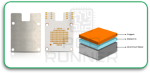
Metal Core PCBs for Heat-Sensitive Applications
Metal core PCBs replace the fiberglass substrate with an aluminum or copper base layer. This dramatically changes the thermal conductivity, from 0.3 W/m·K (FR-4) to 1-9 W/m·K, depending on the metal core used.
Aluminum core: most common, good thermal performance, cost-effective
Copper core: superior thermal conductivity but significantly more expensive
Used in: high-power LED lighting, motor controllers, automotive lighting, power amplifiers
Limitation: not suitable for complex multilayer designs or very fine trace work
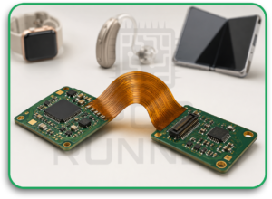
Flexible and Rigid-Flex Materials for Compact Designs
Flexible and rigid-flex materials use polyimide (PI) film as the base substrate instead of rigid fiberglass. Polyimide withstands repeated bending without cracking or delaminating, making it essential for products that must conform to a shape or endure continuous flexing.
Thermal stability: up to 260°C for short-duration exposure
Excellent chemical and radiation resistance
Rigid-flex boards combine rigid sections and flexible sections in one assembly
Used in: wearables, hearing aids, endoscopes, aerospace avionics, foldable consumer devices
Higher fabrication cost due to processing complexity and material cost
PCB Material Comparison Table
| PCB Material | Best Use | Main Strength | Main Limitation | Relative Cost |
| Standard FR-4 | Consumer electronics, computing, industrial controls | Affordable and widely available | Poor choice for high-frequency or high-heat designs | Low |
| High-Tg FR-4 | Automotive, industrial, hotter environments | Better heat tolerance than standard FR-4 | Still not ideal for RF or very high-speed work | Low–Medium |
| Rogers / PTFE | RF, 5G, radar, satellite, microwave | Very low signal loss and stable Dk | Higher cost and more complex processing | High |
| Aluminum Core | LEDs, power electronics, motor controls | Better heat spreading | Limited for complex multilayer routing | Medium |
| Copper Core | High-power and high-thermal applications | Excellent thermal conductivity | Expensive and more difficult to process | High |
| Polyimide Flex | Wearables, medical, aerospace, compact products | Flexible and thermally stable | Higher fabrication cost and process complexity | Medium–High |
| Rigid-Flex | Compact products with rigid and bending areas | Reduces connectors and saves space | More expensive and needs careful design | High |
Key Electrical Properties to Consider When doing PCB Material Selection
Dielectric Constant (Dk) and Its Effect on Signal Speed
Dk tells you how much the material slows down an electrical signal relative to the speed of light in a vacuum. A Dk of 4.0 means signals travel at half the speed they would in free space. Lower Dk = faster signals. For controlled-impedance traces, the Dk of the material is directly used in the impedance calculation. If the Dk varies across temperature or frequency, which it does more in cheaper materials, your impedance targets drift, and signal integrity suffers.
Loss Tangent (Df) and Signal Loss Control
Loss tangent (also called dissipation factor) measures how much energy the dielectric absorbs from a passing signal. A Df of 0.02 (typical FR-4) means notable signal loss at high frequencies. High-frequency materials like Rogers 4003C drop this to 0.0027, nearly 10 times lower loss. At 28 GHz (mmWave 5G frequencies), the difference between FR-4 and a low-Df material is the difference between a working product and a non-functional one.
Impedance Control and Stability
Controlled impedance is critical in high-speed digital designs (USB 3.x, PCIe, DDR5) and all RF work. The material must maintain a consistent Dk across the operating temperature range and across frequency bands. Materials with tight Dk tolerances (±0.05 or better) make it much easier to achieve impedance targets during fabrication. Loose tolerances require more test iterations and increase the risk of out-of-spec boards.
Thermal Properties That Influence PCB Performance
Heat Flow And Thermal Conductivity
Thermal conductivity determines how efficiently the board conducts heat from hot components to heatsinks, chassis, or ambient air. FR-4 at 0.3 W/m·K is a poor thermal conductor. Aluminum-core boards reach 1–3 W/m·K. Copper-core boards can exceed 5 W/m·K. For designs where junction temperature control is critical, LEDs, power transistors, RF power amplifiers, the substrate’s thermal conductivity is a primary selection criterion.
Glass Transition Temperature (Tg) Explained
Tg is the temperature at which the substrate transitions from a rigid, glassy state to a softer, rubbery state. At Tg, the material begins to lose its mechanical and electrical properties. Standard FR-4 has a Tg of around 130–140°C. High-Tg FR-4 extends this to 170–180°C. For automotive underhood electronics or industrial equipment in high-ambient environments, you need a material whose Tg is at least 20–25°C above the maximum operating temperature to maintain a safety margin.
Coefficient of Thermal Expansion (CTE) and Reliability
CTE measures the dimensional expansion of a material when heated. The problem arises when the CTE of the substrate does not match that of the components soldered to it. FR-4 has a Z-axis CTE of around 50–70 ppm/°C above Tg. Through-hole vias and BGA solder joints endure mechanical stress from this mismatch every time the board heats and cools. Over hundreds of thermal cycles, this causes micro-cracking and eventual open circuits, even if the original soldering was perfect.
Mechanical and Environmental Factors You Should Not Ignore
Strength, Flexibility, and Durability
Rigid boards must resist flex, impact, and vibration without cracking traces or delaminating layers. The flexural strength of FR-4 is typically around 550 MPa, which is adequate for most applications. For harsher environments, automotive, aerospace, industrial machinery, verify the specific laminate’s mechanical specifications against your expected load conditions.
Moisture Resistance and Environmental Stability
All substrate materials absorb some moisture. When moisture enters the substrate, the Dk value increases, electrical performance degrades, and the risk of electrochemical migration rises. For boards deployed outdoors, in marine environments, or in medical devices that undergo sterilization, the moisture absorption rate (typically expressed as a percentage weight gain) is a critical specification to check.
Performance Under Harsh Industrial Conditions
Industrial PCBs are exposed to chemicals, vibration, thermal shock, and long operational lifetimes, often 10 to 15 years or more. Materials for these applications need to hold their properties across all these stressors simultaneously, not just in controlled lab conditions.
How PCB Material Selection Affects Manufacturing Cost
Material Cost vs Performance Trade-Off
| Material Type | Relative Cost | Typical Application |
|---|---|---|
| Standard FR-4 | Low | Consumer electronics, computing |
| High-Tg FR-4 | Low–Medium | Automotive, industrial |
| Rogers / PTFE | High | RF, 5G, radar, mmWave |
| Aluminum Core | Medium | LED lighting, power electronics |
| Polyimide (Flex) | Medium–High | Wearables, medical, aerospace |
Rogers laminates can cost 5 to 10 times as much as FR-4 per panel. But using FR-4 in an RF design to save money will result in a non-functional product. The real cost comparison must include failure rates, rework costs, and warranty exposure—not just raw material prices.
Availability and Supply Chain Impact
FR-4 is available from dozens of suppliers globally with very short lead times. Specialty materials, such as PTFE composites or specific Rogers grades, may have longer lead times and minimum order quantities. For high-volume production, material availability must be confirmed before committing to a design.
Processing Complexity and Production Time
PTFE-based materials require special surface preparation before plating. Polyimide flex materials need different lamination profiles than rigid FR-4. Metal core boards require modified drilling parameters. All of this adds fabrication time and requires manufacturer expertise. Confirm that your chosen PCB board manufacturer has documented experience with your specific material before production begins.
Choosing Materials Based on Application Requirements
Consumer electronics: FR-4 is the right choice. Prioritize cost and availability.
Automotive: High-Tg FR-4 or specialty laminates with tight CTE control and moisture resistance. AEC-Q100 environmental testing applies.
RF and telecom: Rogers or PTFE materials only above 2 GHz. Dk and Df tolerances must be specified on the fab drawing.
Industrial equipment: High mechanical strength, moisture resistance, and a Tg well above the operating environment temperature.
Medical and wearables: Polyimide flex or rigid-flex for compact form factors and reliability under repeated mechanical stress.
Design Considerations Linked to Material Selection
Layer Stack-Up Planning
The dielectric thickness between layers, determined by the prepreg and core materials selected, directly affects controlled impedance calculations. Stack-up must be designed in coordination with material choice, not independently of it.
Trace Width and Spacing Based on Material
Different materials have different etching characteristics. PTFE materials require wider trace-to-copper spacing in some processes. Metal-core boards are typically single- or double-sided, which limits routing density. Know the material constraints before routing.
Compatibility with Assembly Processes
Some materials are not compatible with standard lead-free soldering profiles (peak temperature around 260°C). Verify that the material’s thermal ratings align with your assembly process, especially for flex materials and specialty laminates.
Common Mistakes in PCB Material Selection
Choosing Cost Over Performance Without Analysis
Defaulting to the cheapest material for PCBs without analyzing the operating conditions is the single most common mistake. It produces boards that technically pass initial testing but fail in the field.
Ignoring Thermal Requirements
If you have any component dissipating more than about 1W on your board, the substrate’s thermal conductivity should be part of your selection criteria. Most designers check this too late.
Not Aligning Material with Application Needs
A material rated for office temperature operation will not survive automotive underhood temperatures. A rigid board cannot function in a wearable that bends with the user’s wrist. Match material to real-world conditions, always.
Common Failure Cases
RF Board Failing Due to Wrong Material
A board designed for RF or microwave use may pass basic checks but fail in real operation if standard FR-4 is used beyond its reliable frequency range. The usual symptoms include signal loss, poor range, unstable impedance, weak antenna performance, and failed compliance testing.
This is not a layout-only issue. If the Dk and Df values are not suitable for the operating frequency, the board material itself becomes the problem.
Power Board Overheating During Operation
A power board may work during short testing but overheat during long use. This often happens when heat-producing components are placed on standard FR-4 without enough thermal path.
Typical signs include darkened board areas, damaged solder joints, reduced component life, and sudden field failures. In this case, aluminum core, copper core, thicker copper, better thermal vias, or a different stack-up may be needed.
Automotive Board Cracking After Thermal Cycling
Automotive boards face heat, cold, vibration, and repeated temperature changes. If the material has poor CTE control or a low Tg for the operating environment, solder joints and vias can crack over time.
This kind of failure may not appear during early tests. It may appear after months of real-world use.
Flexible Product Failing Because a Rigid Board Was Used
Wearables, medical devices, foldable products, and compact electronics often need flexible or rigid-flex materials. If a rigid board is forced into a bending application, copper traces can crack and the board can fail.
The material must match the movement of the product.
Moisture-Related Leakage in Outdoor or Harsh Environments
Boards used outdoors, near moisture, or in medical and industrial environments can fail if the substrate absorbs moisture. Moisture can change electrical behavior, increase leakage paths, and increase the risk of corrosion or electrochemical migration.
For these designs, moisture resistance should be checked before the material is approved.
Best Practices for Selecting the Right PCB Material
Work with Your Manufacturer Early
Share your operating frequency, thermal environment, mechanical requirements, and production volumes with your manufacturer during the design phase. A capable PCB Runner manufacturing partner will help you narrow the material options to those that are both technically suitable and practically producible.
Validate Material with Prototypes
Always prototype with the actual production material, not a substitute. Electrical performance, thermal behavior, and mechanical durability can only be confirmed with physical testing.
Balance Performance, Cost, and Availability
The right material is not the most expensive one. It is the one that meets your specs, fits your budget, and can be sourced reliably throughout your product’s production life.
Future Trends in PCB Materials
Advanced computing at speeds above 100 Gbps is driving demand for ultra-low-Dk, ultra-low-Df materials beyond what current PTFE composites offer. Hydrocarbon ceramic laminates and next-generation fluoropolymers are being developed specifically for this range. On the sustainability side, halogen-free laminates are replacing traditional FR-4 formulations in response to tightening environmental regulations in Europe and Asia. AI server infrastructure and hyperscale data centers are driving strong demand for materials that support extremely high-speed differential signaling—an area where material development is advancing rapidly.
Conclusion
Material selection is not a formality, it is a core engineering decision that determines whether your PCB succeeds or fails.
Every electrical property, every thermal limit, every solder joint, and every dollar in your warranty budget connects back to what your board is made of. A wrong choice made early in the design process creates problems that no amount of rework or redesign can fully fix.
PCB Runner works alongside engineers and product teams from material selection through full-scale production, helping you make decisions that hold up in the real world, not just on paper.
FAQs
What Is the Most Commonly Used PCB Material?
FR-4 is the most widely used PCB material globally. It offers a solid balance of electrical performance, mechanical strength, and low cost, suitable for the large majority of standard electronic products.
When Should You Choose High-Frequency Materials?
Choose Rogers, PTFE, or similar laminates when your design operates above 1–2 GHz, requires tight impedance control, or must maintain very low signal loss. Common applications include 5G hardware, radar modules, satellite systems, and precision RF instruments.
How Does Material Affect PCB Cost?
Material cost has a direct impact on board price. But material choice also affects yield rates, processing time, and long-term failure rates. A more expensive material that prevents field failures will almost always be cheaper over the full product lifecycle than a cheap material that causes them.
Can Wrong Material Selection Cause PCB Failure?
Yes, it is more common than most people expect. Thermal delamination, solder joint cracking due to CTE mismatch, signal loss at high frequencies, and moisture-induced leakage are all failure modes that trace directly to material selection errors.
Is FR-4 Suitable for All PCB Designs?
No. FR-4 is excellent for general-purpose electronics but is not appropriate for high-frequency RF work, high-heat power applications, or flexible form factors. Always evaluate your actual operating conditions before defaulting to FR-4.

