Rigid-flex PCBs are changing how we design electronic devices. By combining flexible and rigid sections, they allow for compact, durable, and reliable products. If you’re working on a project that requires space-saving and robust circuit boards, understanding the materials and manufacturing processes is crucial.
Understanding Rigid-Flex PCBs
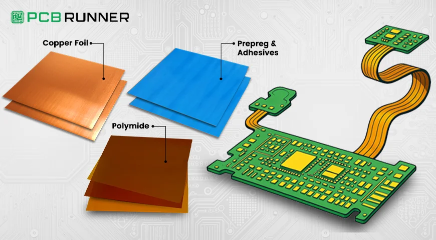
A rigid-flex PCB integrates both rigid and flexible substrates into a single board. The rigid parts provide structural support and house components, while the flexible sections connect different rigid parts, allowing the board to bend and fit into tight spaces. This design reduces the need for connectors and cables, enhancing reliability and saving space.
Key Materials Used
Choosing the right materials is vital for the performance and durability of rigid-flex PCBs.
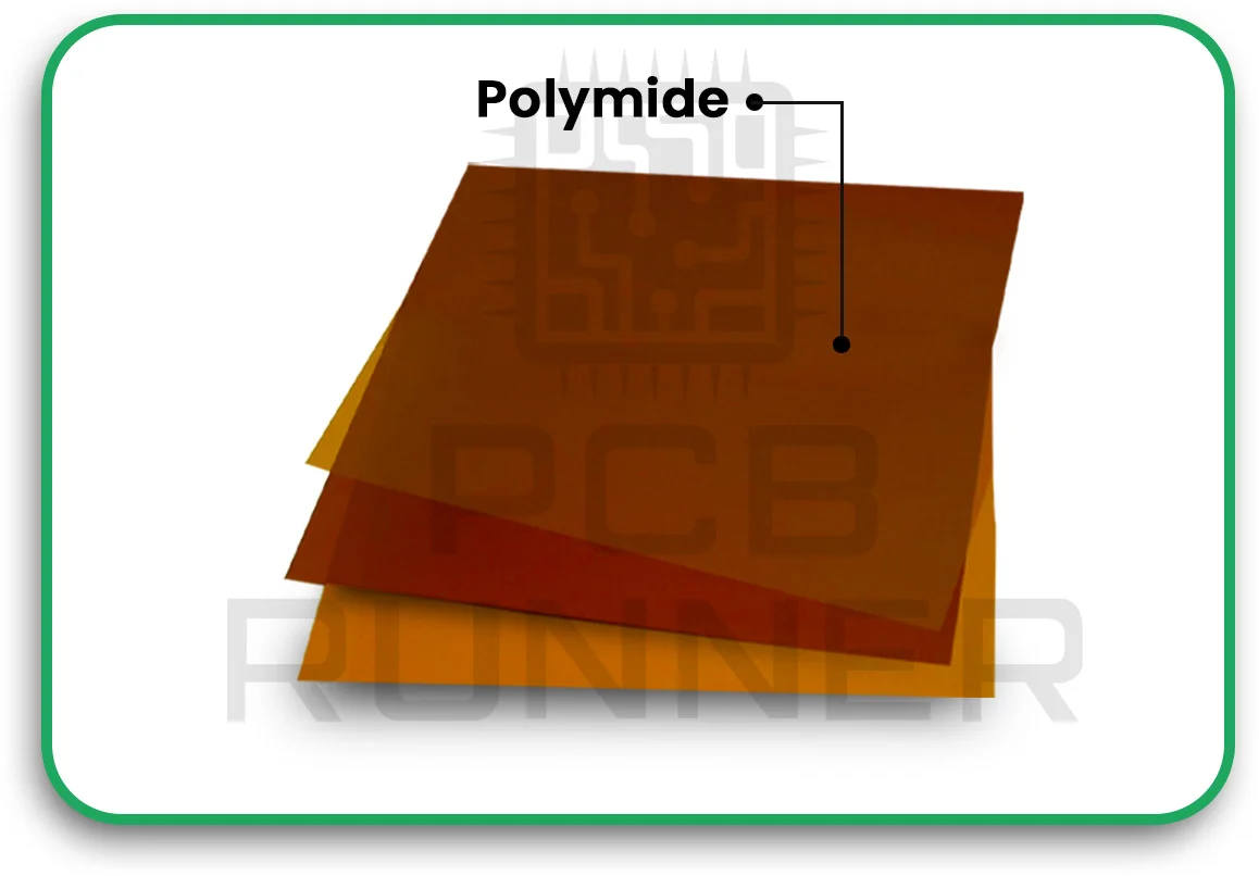
1. Polyimide Film
Polyimide film is the primary material for the flexible sections of the PCB. It’s known for its excellent flexibility, thermal stability, and mechanical strength. These properties make it ideal for applications that require the board to bend without breaking. Polyimide films can withstand high temperatures and are resistant to chemicals, ensuring longevity in various environments.
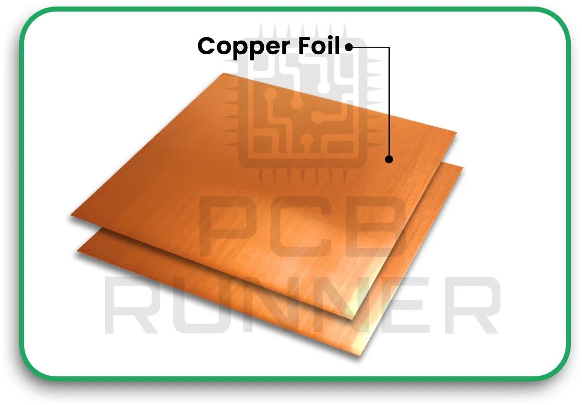
2. Copper Foil
Copper foil is used for the conductive layers in both rigid and flexible sections. In flexible areas, rolled annealed copper is preferred due to its superior flexibility compared to electro-deposited copper. This choice ensures that the conductive traces can endure repeated bending without cracking.
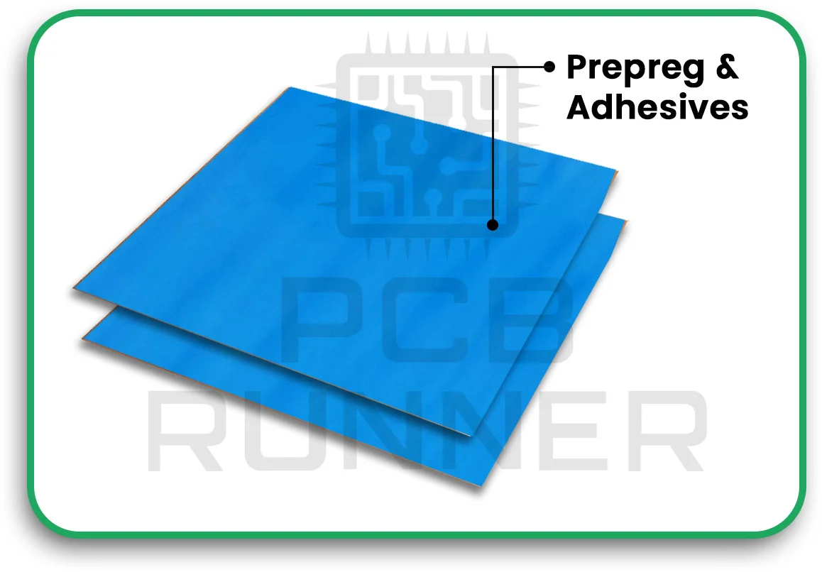
3. Prepreg and Adhesives
Prepregs are resin-impregnated materials used to bond layers together in the rigid sections. They provide mechanical strength and electrical insulation. Adhesives are also used to bond flexible layers, ensuring that the different materials in the PCB stay together under mechanical stress.
Manufacturing Process
The manufacturing of rigid-flex PCBs involves several precise steps to ensure quality and reliability.
1. Design and Layout
The process begins with designing the PCB layout, considering the placement of components, the routing of traces, and the bending areas. Proper design ensures that the flexible sections can bend without stressing the components or the conductive traces.
2. Material Preparation
Materials like polyimide films and copper foils are prepared and cleaned to remove any contaminants. This step is crucial to ensure strong adhesion between layers and to prevent defects.
3. Layer Lamination
The prepared materials are laminated together under heat and pressure. In the rigid sections, multiple layers are bonded using prepregs, while in the flexible sections, adhesives are used to bond the layers. This process creates a unified board with both rigid and flexible areas.
4. Drilling and Plating
Holes are drilled into the board to create vias, which are then plated with copper to establish electrical connections between layers. This step is essential for multi-layer PCBs to ensure proper signal flow.
5. Imaging and Etching
The PCB is coated with a photoresist, and the desired circuit pattern is transferred onto it using UV light. The exposed areas are then etched away, leaving behind the copper traces that form the circuit.
6. Solder Mask Application
A solder mask is applied to protect the copper traces from oxidation and to prevent solder bridges during component assembly. In flexible areas, a coverlay made of polyimide film is used instead of a traditional solder mask.
7. Surface Finishing
Surface finishes like ENIG (Electroless Nickel Immersion Gold) are applied to the exposed copper pads to enhance solderability and protect against corrosion.
8. Testing and Quality Control
The final PCB undergoes electrical testing to ensure all connections are correct and there are no shorts or opens. Visual inspections and other quality control measures are also performed to detect any defects.
Benefits of Rigid-Flex PCBs
Rigid-flex PCBs combine the best of both rigid and flexible circuit board technologies, offering numerous advantages that make them ideal for modern electronic applications. Here’s why they are increasingly preferred over traditional rigid or flexible PCBs:
1. Space Efficiency
One of the most significant benefits of rigid-flex PCBs is their ability to save space and reduce weight. By integrating rigid and flexible sections into one cohesive unit, these boards eliminate the need for connectors, cables, and additional components that would typically link separate rigid boards. This streamlined design not only saves physical space but also minimises the overall weight of the final product, making it particularly useful in compact and lightweight applications such as wearable electronics and mobile devices.
2. Enhanced Reliability
Because rigid-flex PCBs reduce the number of interconnections between different board sections, they inherently have fewer points of failure. In traditional setups, connectors and solder joints are prone to damage and wear, especially under mechanical stress or vibration. By combining flexible and rigid parts into one integrated structure, rigid-flex PCBs eliminate many of these weak spots, significantly improving the overall reliability and durability of the device. This makes them an excellent choice for mission-critical applications such as aerospace, military, and medical devices.
3. Design Flexibility
The unique structure of rigid-flex PCBs allows for innovative and efficient product designs. These boards can bend, fold, or twist to accommodate complex shapes and compact spaces without sacrificing connectivity or performance. This flexibility is essential in products where space optimisation is crucial, like medical implants, smartphones, and compact computing devices. Designers can take advantage of the flexible sections to create more ergonomic and functional product layouts.
4. Cost Savings
While the initial manufacturing cost of rigid-flex PCBs may be higher than that of standard PCBs, the long-term savings can be substantial. By reducing the need for connectors, cables, and additional assembly steps, manufacturers can decrease production costs. Moreover, the increased reliability and durability of these boards translate into fewer maintenance and replacement costs over the product’s lifespan. Thus, despite the upfront investment, rigid-flex PCBs can lead to significant cost efficiency in the long run.
5. High-Performance Applications
Rigid-flex PCBs are particularly suited for high-performance and harsh environment applications. Their robustness against mechanical stress, combined with their lightweight and compact design, makes them ideal for use in industries that demand both durability and efficiency, such as automotive, aerospace, and industrial automation.
Choosing the Right Manufacturer
When selecting a manufacturer for your rigid-flex PCBs, consider the following:
- Experience: Choose pc board manufacturers with a proven track record in producing flex and rigid PCBs.
- Quality Control: Ensure they have stringent quality control processes to detect and rectify defects early.
- Technical Support: A manufacturer that offers design assistance can help optimise your PCB for performance and manufacturability.
- Certifications: Look for manufacturers with relevant certifications, indicating adherence to industry standards.
Conclusion
Rigid-flex PCBs are revolutionising the electronics industry by enabling more compact, reliable, and innovative designs. Understanding the materials and manufacturing processes involved is essential for leveraging their full potential. By selecting the right materials like polyimide film and partnering with experienced pc board manufacturers, you can ensure the success of your circuit board assembly projects.
Embrace the advantages of flex and rigid PCBs to stay ahead in the rapidly evolving world of electronics.

