Objective:
Give engineers and product teams a clear, technically grounded understanding of rigid-flex construction, when it’s the right call, and what actually goes into building one correctly.
Key Takeaways
- A Rigid-Flex PCB combines rigid board sections with flexible circuit layers bonded into one continuous structure, removing the need for separate connectors between them.
- Eliminating connectors is the single biggest reliability gain, since connector joints are one of the most common failure points in vibration-heavy environments.
- The US Defense Logistics Agency qualifies rigid-flex fabricators under MIL-PRF-31032, a standard that governs board construction for military and aerospace programs.
- Bend radius, layer stack-up, and material selection at the flex-to-rigid transition are the three design details that cause the most re-spins.
- Rigid-flex costs more upfront than a standard rigid PCB paired with a wire harness, but often costs less over the product’s full life once assembly labor and failure rates are factored in.
An engineer building a handheld device runs out of room. The rigid board handles the processor and connectors fine, but the display needs to sit at an angle, and there’s no space left for a ribbon cable connector without adding another two millimeters to the enclosure. This is the exact problem rigid-flex construction was built to solve, and it comes up constantly in compact, high-reliability products.
The US Defense Logistics Agency qualifies manufacturers for rigid, flex, and Rigid-Flex PCB production under MIL-PRF-31032, a federal standard covering construction, testing, and traceability for boards used in military and aerospace hardware. That level of scrutiny exists because rigid-flex boards often end up in products where a connector failure isn’t just inconvenient, it’s mission-critical.
This guide covers how rigid-flex boards are built, where they genuinely earn their higher price tag, and where they don’t.
What Is a Rigid-Flex PCB?
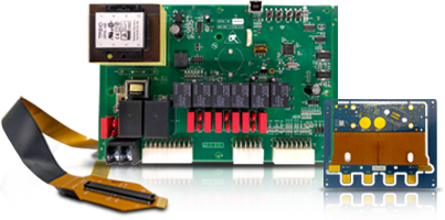
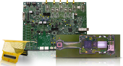
A Rigid-Flex PCB is a circuit board that combines rigid sections and flexible sections into a single, permanently bonded structure. The rigid areas hold components. The flexible areas bend, fold, or wrap to fit the product’s shape.
Picture two rigid boards connected by a ribbon cable, except the ribbon cable isn’t a separate part plugged into connectors. It’s built directly into the board itself, using the same copper and lamination process as the rigid sections. That’s the core idea behind Rigid-Flex PCBs: the flex layer is part of the board, not an accessory attached to it.
Most rigid-flex constructions place plated through-holes only in the rigid sections, since drilling through a flexible polyimide layer weakens it considerably. Components mount on the rigid areas, while the flex sections handle interconnection and, in some designs, dynamic bending that happens repeatedly during the product’s normal use, like a hinge in a folding device.
How Does Rigid-Flex PCB Design Work?
Rigid-flex PCB design starts with mapping out which sections of the board need to stay rigid and which need to bend, then building a layer stack that supports both without one compromising the other.
A few decisions drive most of the design work:
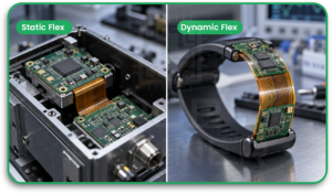
- Bend type. A static flex bends once during assembly and then stays put. A dynamic flex bends repeatedly over the product’s life, like in a wearable strap, and needs different copper foil and thicker coverlay to survive fatigue cracking.
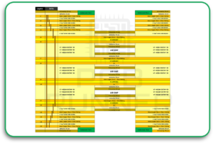
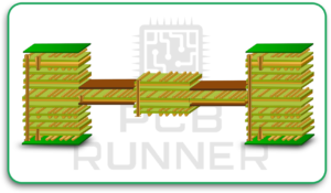
- Layer stack-up. Rigid sections typically use standard FR-4 cores bonded with prepreg, while flex sections use polyimide film, which handles repeated bending without the brittleness that FR-4 has.
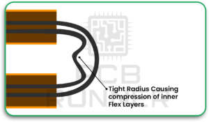
- Bend radius. The minimum radius a flex section can bend without stressing the copper traces depends on copper thickness and layer count. A common rule of thumb is a bend radius of at least 10 times the flex thickness for static applications, more for dynamic ones.
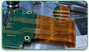
- Transition zones. The area where rigid meets flex is the most failure-prone spot on the board. Traces routed straight across this boundary, without a taper or stress relief, are a common cause of cracked copper during assembly or field use.
- Coverlay application. Instead of solder mask, flex sections use a polyimide coverlay bonded with adhesive, which protects the copper while staying flexible enough to bend with the board.
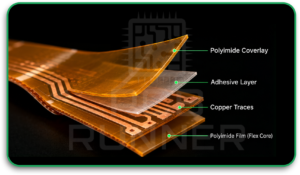
Getting the stack-up wrong here is expensive. A design that looks fine on screen but ignores bend radius or transition zone stress will fail mechanical testing, and by then the tooling is already built.
What Are the Benefits of Rigid-Flex PCBs?
The core rigid-flex PCB benefits come down to fewer parts, less weight, and higher reliability, which matters most in products where space and failure rate both carry real consequences.
- Fewer connectors. Every connector is a potential failure point, especially under vibration. Removing them cuts down on one of the most common causes of field failures in mobile and aerospace electronics.
- Reduced weight and volume. Cutting cable harnesses and connector housings shrinks both the size and weight of the final assembly, which matters directly in aerospace and wearable products where every gram counts.
- Better signal integrity. A continuous copper trace through the flex section performs more predictably than a trace broken by a connector interface, particularly for high-speed or sensitive analog signals.
- Simplified assembly. Fewer discrete parts means fewer assembly steps and fewer chances for a technician to make a wiring error during the final build.
- Design freedom. Products with unusual shapes, folding mechanisms, or multiple board planes can use rigid-flex to route signals between sections without designing around bulky cable routing.
These rigid-flex PCB advantages show up most clearly in products that get dropped, shaken, or flexed repeatedly, since that’s exactly where connector-based designs tend to fail first.
Where Are Rigid-Flex PCBs Used?
Real rigid-flex PCB applications span any product where space is tight, reliability requirements are high, or both.
- Military and defense. Guided systems, avionics, and portable communication gear all favor rigid-flex because it survives vibration and shock better than a connector-heavy alternative.
- Aerospace. Satellite systems and onboard avionics use rigid-flex to save weight, since every gram launched into orbit carries a real cost.
- Medical devices. Hearing aids, endoscopes, and implantable devices need boards small enough to fit tight enclosures without sacrificing reliability, since a field failure isn’t just an inconvenience.
- Wearables. Fitness trackers and smartwatches use dynamic flex sections that bend continuously as the device is worn, which is exactly the kind of repeated stress rigid-flex is engineered to handle.
- Automotive. Advanced driver-assistance systems and in-vehicle connectivity modules use rigid-flex to fit sensors and processors into compact housings near the dashboard or steering column.
PCB Runner builds flex and rigid-flex boards for exactly these industries, supporting single and double-sided flex circuits along with multilayer rigid-flex constructions up to 20 layers.
What Challenges Come With Rigid-Flex Manufacturing?
The main rigid-flex PCB challenges center on cost, lead time, and the precision required to bond dissimilar materials into one working board.
- Higher upfront cost. Rigid-flex requires more process steps, more specialized materials, and tighter tolerances than a standard rigid board, which drives the price up before a single component gets placed.
- Longer lead times. Lamination cycles for combined rigid and flex layers take longer than standard multilayer fabrication, and design review tends to take longer too, since more can go wrong.
- Design complexity. Engineers without prior rigid-flex experience often underestimate bend radius requirements or place components too close to a flex transition zone, both common causes of costly re-spins.
- Limited manufacturer options. Not every PCB fabricator has the equipment or process control needed for reliable rigid-flex production, which narrows the supplier pool compared to standard rigid boards.
- Repair difficulty. A defect in a flex section is harder to rework than a defect on a standard rigid board, since the flexible material doesn’t tolerate repeated rework heat cycles as well.
Working with a fabricator who reviews your design before production, rather than after the first bad batch comes back, avoids most of these problems.
Rigid-Flex vs. Rigid PCB With a Wire Harness
A standard rigid PCB connected to another board through a wire harness is cheaper to build initially and easier to source from almost any fabricator. It’s a reasonable choice for low-volume products or designs where space isn’t tight.
Rigid-flex costs more to build, but it removes the connector failure risk entirely and cuts down on assembly labor, since there’s no harness to route, crimp, and inspect separately. For products built in volume, or products that need to survive years of vibration without a field failure, that trade often favors rigid-flex once total lifecycle cost gets factored in, not just the unit price on day one.
The right choice comes down to volume, reliability requirements, and how much space the enclosure actually allows. A low-volume prototype rarely justifies the tooling investment rigid-flex requires. A product shipping in the thousands, headed into a harsh environment, usually does.
Conclusion
Building a rigid-flex board that survives years in the field comes down to getting the transition zones, bend radius, and layer stack right before fabrication starts, not fixing it after a batch fails testing. PCB Runner has supported rigid-flex projects for military, medical, and aerospace OEMs for years, with an engineering team that reviews designs from the early stack-up stage through to production. If you’re planning a rigid-flex build, request a free quote and get engineering feedback on your design before you commit to tooling.
FAQs
Q. How much more does a Rigid-Flex PCB cost compared to a standard rigid board?
Rigid-flex typically runs two to four times the cost of an equivalent rigid board, mainly due to specialized materials and longer lamination cycles. The gap narrows at higher volumes as tooling costs get spread across more units.
Q. What’s the minimum bend radius for a flex section?
A common starting rule is 10 times the flex thickness for a static bend that only flexes once during assembly, and closer to 20 times or more for a dynamic bend that flexes repeatedly. Your fabricator should confirm exact numbers based on your specific layer stack.
Q. Can rigid-flex boards be reworked if a component fails?
Rework is possible on the rigid sections using standard desoldering methods, but flex sections need lower heat exposure and more careful handling to avoid damaging the polyimide layer. Repeated rework on a flex area increases the risk of cracking.
Q. Do all Rigid-Flex PCB manufacturers use the same materials?
No. Flex sections almost always use polyimide film, but coverlay thickness, adhesive type, and copper foil grade vary between fabricators, and those choices affect how well the board survives repeated bending. Ask your supplier directly about their standard flex stack-up.
Q. Is rigid-flex worth it for a low-volume prototype?
Usually not, unless the product genuinely can’t fit a connector-based design into the available space. The tooling and material costs for rigid-flex make more sense once a design moves toward production volume.