Every electronics industry professional today understands the requirement of a reliable PCB design that meets EMC standards. To keep up with the power and compactness of new devices one must keep in mind the risk of electromagnetic interference (EMI) that can truncate the overall performance.
Thus, every PCB manufacturer or designer must tackle the challenges of an interference-free operation while designing the PCB layout, which is critical to a PCB design achieving EMC standards.
This blog will discuss the key principles of electromagnetic compatibility and offer tips to manage EMI and overall performance. It is crafted not only for seasoned PCB manufacturers but also for designers aiming to polish their skills in creating layouts and meeting EM standards.
Why Electromagnetic Compatibility Matters in PCB Design
A PCB is always designed with certain electronic components. Thus, electronic interference and electromagnetic noise are always monitored. A power supply must provide a reliable and smooth output without interference from external systems and devices.
In the context of PCB layout design, poor EMC design can lead to:
- Undesirable signal interference.
- Unwanted crosstalk.
- Not achieving set regulatory standards.
- Additional expenses from redundant tests and new designs.
- Focusing on EMC during the design of a PCB layout helps you avoid mistakes that compromise product quality and compliance.
The Important Parts of PCB Layout Design Covering EMC Compliance
1. Design of Ground Plane
A complete ground plane is the starting point of all EMC-compliant PCB layouts. Ground planes reduce noise and emissions because they provide low impedance returns for signals. Optimize your ground planes:
- Split or gap-free continuous ground planes.
- Create ground loops that can act as EMI antennas.
- Use direct connections from all ground locations to the ground plane.
2. Trace and Signal Management
Improper routing can compromise EMI containment. It is essential to follow these rules:
- Place all high-speed signal trace endpoints close to the circuit.
- Ensure power supplies do not emit noise-sensitive signal routing.
- Use noise-cancelling differential pairs for other high-speed signals.
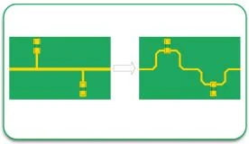
- In traces never use sharp angles to avoid signal needlessly bouncing.
3. Placement of the Components
Considerations regarding component placement help reduce emissions considerably. You should ensure the following.
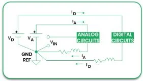
- Tools and equipment should be grouped functionally. For example, analogue, digital, and power circuits.
- Sensitive circuits should be placed at a distance from noisy tools like switching regulators.
- Noise from power pins can be suppressed by placing decoupling capacitors in close quarters.
4. Power Distribution Network (PDN) Design
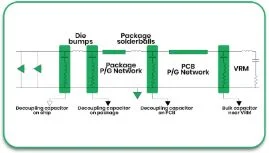
Appropriate PDN design greatly ensures power delivery and minimizes electromagnetic interference. Some pointers to keep in mind are:
- Use several vias to connect to the power and ground planes.
- Utilize decoupling capacitors to suppress high-frequency noise.
- Reduce the loop area of power traces to lower emissions.
5. Shielding and Enclosure Design
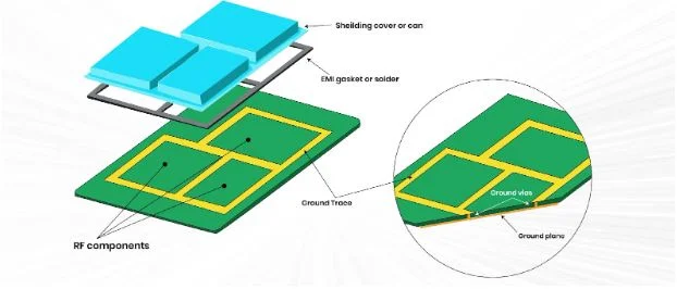
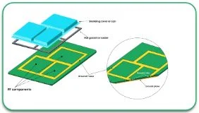
Shielding does not often form part of the PCB arrangement structure, but it is crucial for EMC. You need to collaborate with your PCB vendor to implement the shielding requirements, such as:
- Metal enclosures that contain the source of interference.
- Solders cans for covering sensitive parts.
- Conductive gaskets fill the enclosure gaps.
Further Methods of EMC Improvement
1. Impedance Matching
Reflective signal responses can create interference. Improper impedance matching is usually the cause. To ensure proper matching, follow these:
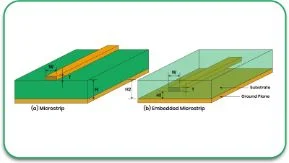
- Determining the trace impedance using the material parameters.
- Impedance-controlled routing on the traces for the speed signals.
2. Split Planes for Mixed-Signal Designs
In mixed designs, the ground plane can be separated to help isolate the analogue and digital circuits, but this must be done with great precision to avoid creating ground loops.
3. EMI Filters
EMI filters are designed especially to eliminate electromagnetic interference in specific appliances. Some common filters are:
- Ferrite beads.
- LC filters.
- Common mode choke.
Mistakes to Avoid in PCB Layout Design
Designers often make errors that can directly affect EMC. Here are some of the most noted mistakes that designers should be aware of:
- Insufficient Ground Attachment: Weak connections to the ground can cause more EMI as well as noise.
- Failure to Use Decoupling Capacitors: Not including decoupling capacitors or using the wrong capacitor value can introduce noise to the power supply.
- Disregarding Return Paths for the Signal: Not considering return currents can lead to the creation of EMI hotspots.
- Ignoring Thermals: Ultrasonic components can produce thermal noise, which can impact EMC.
Finding the Best PCB Manufacturer
Getting proper EMC compliance is not only dependent on the design stage but also relies on the skills of your PCB manufacturer. A knowledgeable manufacturer can facilitate your work by:
- Choosing appropriate materials for your design.
- Using better manufacturing processes to lessen EMI.
- Performing proper testing to check support for EMC requirements.
At PCB Runners, we are known for providing high-quality PCBs and ensuring compliance with EMC regulations. We work with our clients to proactively adjust the PCB layout design to enhance functionality, reliability, and compliance.
Conclusion
Creating PCB designs that accommodate electromagnetic compatibility is challenging, but it is necessary. With these principles in mind, you can create designs that do not emit unnecessary EMI, tend to signal integrity and adhere to regulations. Each step, from ground plane layout to component placement, is critical to achieving EMC compliance.
Having a reliable PCB manufacturer such as PCB Runners grants you an advantage. Your design will be flawless since PCB Runners specializes in layout design and manufacturing and greatly understands that the boards have to work in challenging situations.
Are you prepared to elevate your PCB designs? Contact PCB Runners to see how we can assist you in attaining EMC compliance and improving the effectiveness of your designs.
FAQs
1. What is electromagnetic compatibility (EMC) in PCB design?
EMC allows a PCB to function without causing or being affected by electromagnetic interference.
2. How does ground plane design affect EMC?
A solid ground plane minimizes the noise and provides a return path for signals that improve EMC.
3. Why is component placement important for EMC?
Properly placed components reduce interference for noisy circuits with sensitive ones, thus greatly reducing the EMI.
4. What do the PCB producers do from their side to ensure EMC compliance?
A proficient PCB producer can aid in design improvement, material selection, and testing for compliance with the standard regulations on EMC.
5. What are the best practices for minimizing EMI issues in high-speed PCB designs?
Impedance matching, coupling through differential pairs and active decoupling are some of the means to minimize EMI in such designs.

