Introduction
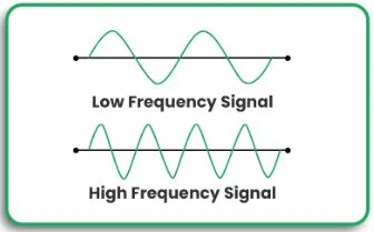
Prior to constructing high-frequency printed circuit boards (PCBs), it is crucial to create a prototype. Such PCBs have applications in telecommunications, aerospace, and medical devices, where quality and operating efficiency are important areas of focus. Having a dependable and accurate PCB prototype helps resolve most of the potential problems before bulk production begins.
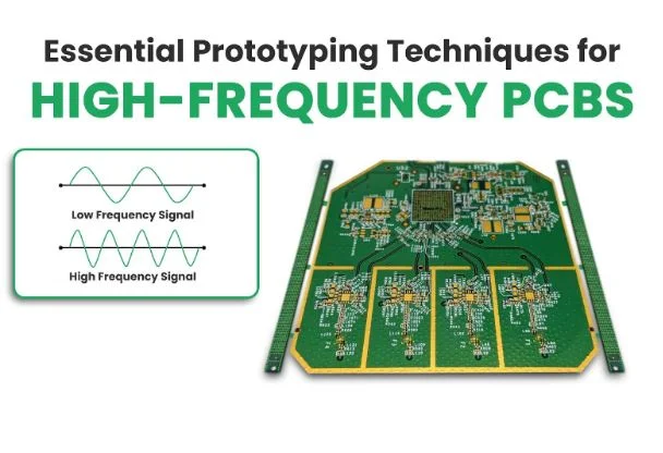
In this article, we explore the critical prototyping techniques used in the development of high-frequency PCBs, the impact of best practices, and innovations in design and performance, such as rigid-flex PCBs.
Here’s What You Need To Know
Concepts of Prototyping on High-Frequency PCBs
The following is what to look out for when prototyping a PCB of a high frequency:
- Choose A Material: Opt for Rogers laminates, which are low-loss dielectrics, to reduce signal strength and impedance variations.
- Control the Impedance: It is critical to maintain consistent impedance to avoid signals reflecting back and losing integrity.
- Optimize Layer Stackup: The PCB design must consider the structure of layers to control EMI and lessen crosstalk.
- Optimize Vias: Employ blind, buried, and micro vias to reduce parasitic inductance.
- Routing Traces: To improve signals, use controlled-impedance traces with matched lengths, reduced bends, or avoided right-angle bends.
- Thermal Management: Heat dissipation techniques should be utilized to improve high-frequency circuit stability.
- Test and Validation: Obtaining an accurate performance read with TDR and VNA guarantees enhanced testing techniques.
Benefits and Application
The following are the salient features of this section’s focus on prototyping techniques for high-frequency PCBs.
- Improved Signal Integrity: Misbalanced impedance and poor routing of traces heavily distort signals and cause them to be lost.
- Reduced Development Costs: It saves time and resources if flaws are spotted early in the design stage.
- Enhanced Design Flexibility: Rigid-flex PCB designs increase constructional load but make the board lightweight and compact, which is helpful in fast-moving scenarios.
- Scalability: A properly designed PCB prototype can transition effortlessly with few alterations to mass production.
By applying these techniques, engineers can create more affordable but dependable high-frequency PCB designs that satisfy the industry’s requirements.
Expert Insights
Designing embedded systems with high-frequency components involves several complex challenges, particularly when incorporating both analog and digital signals. Mixed-signal design issues, such as signal integrity, power integrity, and electromagnetic interference (EMI), are common in systems with components like WiFi, BLE, or Ethernet interfaces. \
To tackle these, board designers must focus on key aspects like stack-up design, component placement, and routing. The goal is to isolate high-frequency digital and analog signals, ensuring that they do not interfere with each other, particularly when dealing with RF functionality.
Proper grounding and isolation of different sections within the PCB layout can minimize crosstalk and signal degradation, leading to more reliable and efficient designs. Furthermore, a high-layer count stack-up is often necessary to accommodate both high-speed digital interfaces and analog components, ensuring impedance control and power integrity.
In addition to the foundational design considerations, designers must pay close attention to the routing of high-frequency signals. Techniques such as coplanar waveguide routing and stripline routing on dedicated layers can prevent interference and ensure signal quality. It is also essential to track return paths carefully and keep RF interconnects isolated from digital components.
Evaluating the design using advanced tools like field solvers before prototyping can help detect potential issues with signal and power integrity. These tools calculate crucial parameters such as impedance matching, network parameters, and radiated EMI, ensuring that the final design meets high-frequency performance standards.
By addressing these challenges early in the design process, engineers can create high-performance embedded systems with seamless analog and digital integration.
Frequently Asked Questions
1. What materials work best for high-frequency PCBs?
For instance, Rogers, Isola, and Taconic laminates are all capable of providing low dielectric loss and stable performance at high frequencies.
2. What steps do I take to achieve controlled impedance on my PCB sample?
Accurate trace width calculations, the controlled impedance stack-up technique, and simulation software achieve controlled impedance.
3. Why would one opt for rigid-flex PCBs in high-frequency operations?
The design is favored for compact designs, superior signal quality, and superior resistance to harsh environments.
4. In what ways are via configurations relevant to PCB high-frequency performance?
Vias should be properly placed and selected (blind, buried, or micro vias) to reduce signal loss and other parasitic effects.
5. Is there a benefit to building a thermal prototype?
Adding thermal vias, heatsinks, and specific components can greatly help manage heat.
Conclusion
Mastering essential prototyping techniques for high-frequency PCBs is vital for achieving optimal performance and reliability. Whether you’re working on RF applications or high-speed digital circuits, paying attention to material selection, impedance control, and testing ensures a successful outcome.
Looking to enhance your PCB prototyping process? Explore our advanced solutions or contact us for expert assistance!

