Almost all electronic devices today use a printed circuit board (PCB). Unfortunately, a printed circuit board that is carefully designed and assembled may sometimes malfunction. At this junction, you may have to employ PCB troubleshooting techniques to repair and resolve issues in the shortest time possible. This is especially the case while working on prototypes or bulk orders from trusted assembly manufacturers. Knowing how to debug your PCB is critical in this case.
In this blog, we will highlight the problems associated with PCBs and the solutions that anyone can perform. Methods and tools will be discussed, ranging from basic visual inspections to complex electrical tests. You will learn to diagnose numerous issues and how to isolate problems. Whether you are a beginner or have some experience, these techniques will enable you to resolve circuit board issues more efficiently.
What Is PCB Troubleshooting?
Troubleshooting printed circuit boards, or PCB troubleshooting, is the process of identifying and removing issues that prevent a printed circuit board from functioning accurately. This is often the case after receiving the assembled board, whereby several faults may be present. For instance, the circuit may fail to power on, some components may fail to respond, or some signals may act abnormally.
Every problem requires a definite order of actions to solve it. Start with basic things first before moving on to more complex things. Imagine a detective trying to solve a case; you need to piece together clues to resolve the problem at hand.
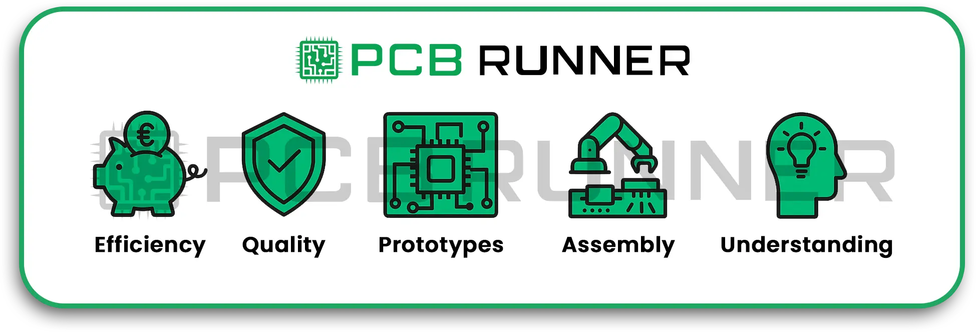
Why is it Important to Solve Troubleshooting Issues on PCBs?
- Saves time and money: Notice issues early on to avoid expensive redesigns or recalls of the product.
- Ensures product quality: The ability to troubleshoot enhances the reliability of electronic products.
- Speed up prototyping: Working on a PCB prototype comes with a lot of issues that need to be resolved rapidly.
- Supports complete turnkey assembly: When you order from circuit board suppliers in the UK & Europe, understanding troubleshooting helps to assure the quality of the order.
- Deepen understanding: troubleshooting builds a stronger grasp on how the circuit operates and aids future projects.
Common Issues Found on PCB Troubleshooting
Before attempting to solve issues, it is essential to be aware of the faults you might come across:
- Open circuits: Paths that are straight but broken.
- Short circuits: Unwanted connections that alter the typical passage of current.
- Wrong placement of components: Parts that are installed on the wrong pads or orientation that is flipped.
- Cold solder joints: Weak connections due to poor soldering.
- Burnt components: Damaged parts that are considered faulty.
- Faults in power supply: Voltage drops or instability in power rails.
- Integrity issues with signals: Distortion and noise due to poor wiring.
- Firmware or software bugs: Issues that are caused due to coding on the board.
At pcbrunner, we minimize these troubleshooting headaches by applying strict manufacturing controls, thorough testing, and design-for-manufacturing reviews so your boards work as intended from the start.
Essential Gadgets Needed for PCB Hardware Debugging
You don’t want to purchase a whole lab setup to get started. Initially, having a few tools is enough and can be expanded upon:
- Multimeter: Measures voltage, resistance, and continuity.
- Oscilloscope: Used to view waveforms and their shapes.
- Magnifying glass or USB microscope: For a magnified view of microscopes and solder joints.
- Power supply with current limiting: Used to power a board with a low risk of damage.
- Logic analyzer: Used for checking and decoding complex digital signals.
- Thermal camera/ IR thermometer: Used to detect components that possibly overheat.
- Tweezers and small tools: Tools used to hold small parts that require magnification to be seen.
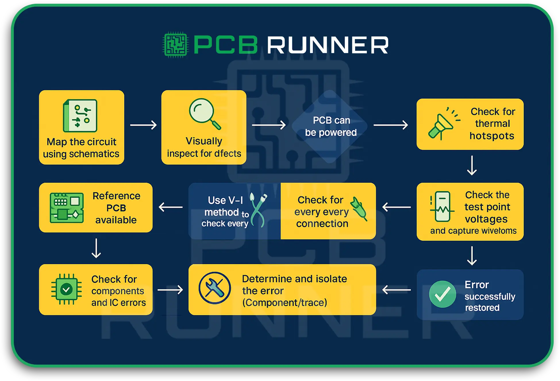
Block-by-Block Steps on PCB Troubleshooting Techniques
1. Start by looking closely
Most PCB problems arise from easily overlooked issues. Here are a few of them:
- Broken or lifted traces: Looking for marks and scratches on copper with a magnifying glass.
- Solder bridges: Pops of solder that are adjacent and blobbed along with solder.
- Cold solder joints: Joints that are connected by solder that is dull or cracked.
- Foreign debris: Shorts caused by dust and metal that is unwanted.
- Overheat burn: Looking for signs of damage or things that are overworked and burned.
Finding and fixing problems visually saves time and effort down the road.
2. Basic Tasks with a Multimeter
Your multimeter can also come in handy for simple tasks with electricity:
- Continuity test: Make sure the two points that should be connected are connected. A multimeter that beeps indicates a connection. These tests help for open and short circuits.
- Resistance measurement: Test suspicious points to see if there is low or high resistance.
- Voltage measurement: Carefully power the board and measure key components and essential rails to check for supply voltages.
Before complex tools are needed, you can focus on problem areas using a multimeter.
3. Cautiously Observe While Powering Up
It is essential to carefully power the board as it may be damaged due to existing faults. Follow these suggestions:
- Employ a current-limited power supply to help prevent burnouts.
- Pay attention to anything unusual that may overheat.
- Listen and smell for burning, which indicates shorts and failed components.
- Use LEDs or test points to determine if critical areas are powered.
This step should never be rushed, as sometimes, due to a power issue, several faults tend to be caused that cascade.
4. Focusing on Signal Checking with an Oscilloscope
If functionality appears to be off, check signal waveforms:
- Are the voltage levels at the expected places?
- Is the timing correct? (rise and fall times)
- Is there signal noise or ringing?
- Use triggers to capture transient mistakes.
- Using oscilloscopes allows you to validate the logic, confirming that he made the proper validations that were needed while working on the PCB.
5. Reviewing the Digital Signals with the Logic Analyzer
In cases where the board has I2C or SPI or UART, the board contains I2C or SPI boards, the board necessitates the use of logic analyzers, hence we:
- Capture multiple signals and do it at the same time.
- Decode the communication made.
- Detect or measure the timing and any data errors.
This is vital and fundamental for the use of microprocessors during the testing of the PCB prototype.
6. Examine and Restyle the Solder Joints
In the presence of bad solder joints, there is always the use of:
- The use of a soldering iron to reflow the joints.
- Use of a solder wick to get rid of bridges.
- And, the use of flux enables the solder process to flow better.
- Good joints remain vital in the electronics domain and correct undead devices as per the working.
7. Software and Firmware Examination
In the presence of PCBs having programmable devices:
- Confirm if the firmware has been flashed the right way.
- Confirm the correct way with debugging tools while processing the code.
- Confirm the running of the software with good hardware to know the defects.
In some cases, it is the software that causes the entire facade of the hardware failures.
Tips for PCB Troubleshooting Success
- Document everything: Capture notes and take photos during the debugging for future reference.
- Divide and conquer: Take problems on the board in sections so as to lessen the workload.
- Stay organized: Maintain a neat work area that is well-lit, has all the required tools.
Contact our sales engineer at sales@pcbrunner.com to discuss design goals, get a production estimate or explore how our pcb prototype expertise can streamline your next build.
Conclusion
Troubleshooting a PCB does not have to be a stressful experience. Follow the steps of inspection, measurement, powering the device, and analyzing signals, and you will be able to fix most of the hardware issues.
Here at PCB Runner, we maintain a high standard of quality from prototyping to full production. However, knowing the PCB troubleshooting tips provided will help you get the most out of your boards, no matter what stage you are at.