Turning abstract designs of printed circuit boards (PCBs) into real, working products involves many tasks and requires attention to detail. This intricate process is something that both engineers and PC board manufacturers focus on to ensure seamless functionality.
PCB Runners specializes in printed circuit assembly, which has become a central activity for the company as it enables quick, dependable, and effective assembly of PCBs according to the drawing provided and functional specifications.
We will simplify the PCB assembly process by designing the board assembly and then the case. If you are looking to make new prototypes or limited series, this is a good starting place, significantly to gain a better perspective of the steps involved.
PCB assembly is an important aspect of consumer, medical, automotive, and industrial electronics, as it is used in key industries.
Understanding these processes will aid those working on them in achieving high-quality production efficiently.
Key Information
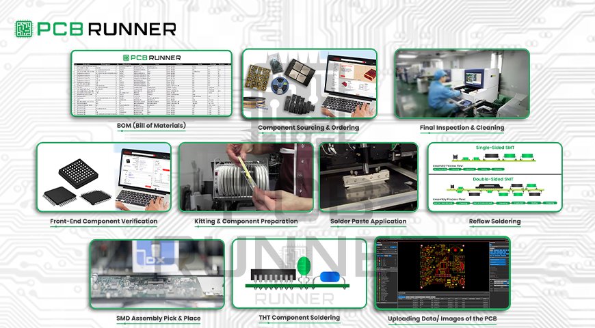
The entire process of assembly technology is captured in this diagram sequentially. Below are the steps on how it is performed:
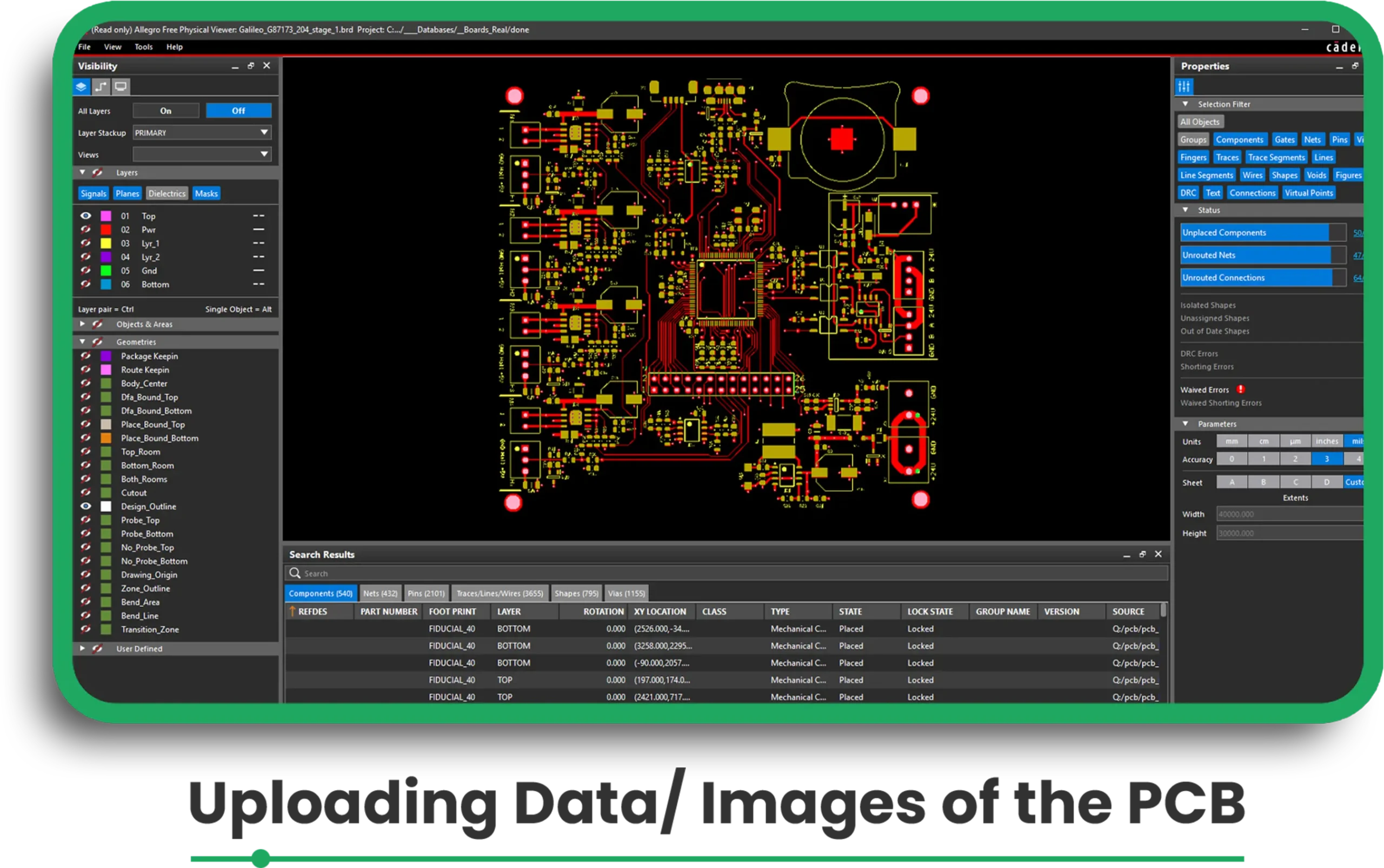
Step 1: Uploading Data/ Images of the PCB
eC-smart tools such as the PCB Visualizer have enabled engineers to check their designs before the assembly phase commences.
The company has to upload the images of the bare board for processing.
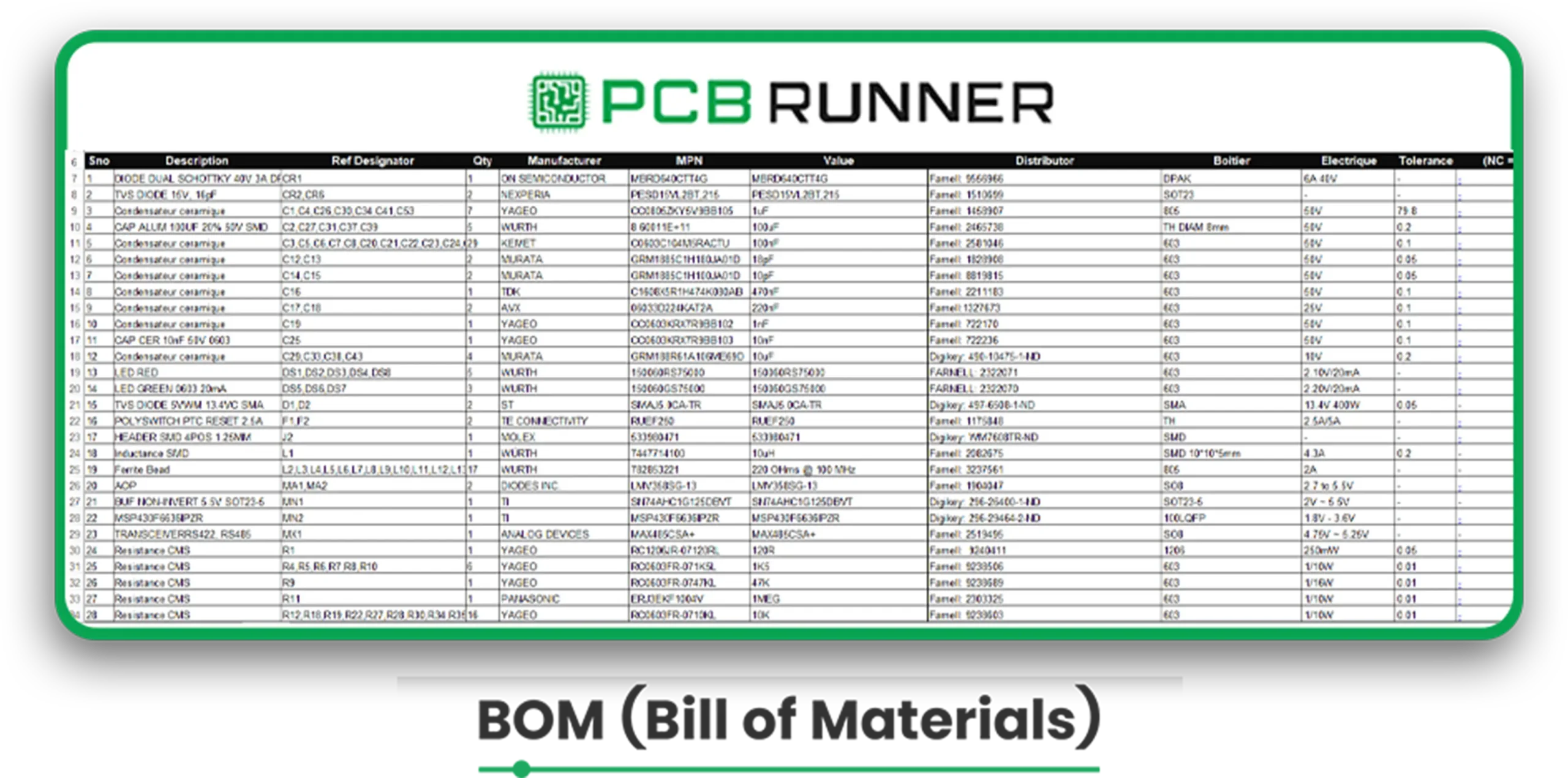
Step 2: Uploading BOM and CPL Files
The BOM (Bill of Materials) includes all component items, such as part number, description, and packaging.
The Component Placement List (CPL) describes the location of all components on the board.
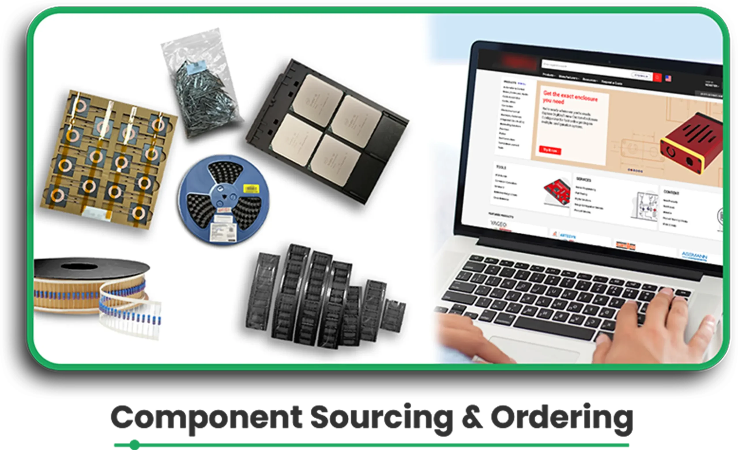
Step 3: Component Sourcing and Ordering
An integrated system scans the BOM against the database of over 205,000 components to look for stock coverage.
If components are not stocked, they need to be ordered from reputable suppliers through integrated APIs.
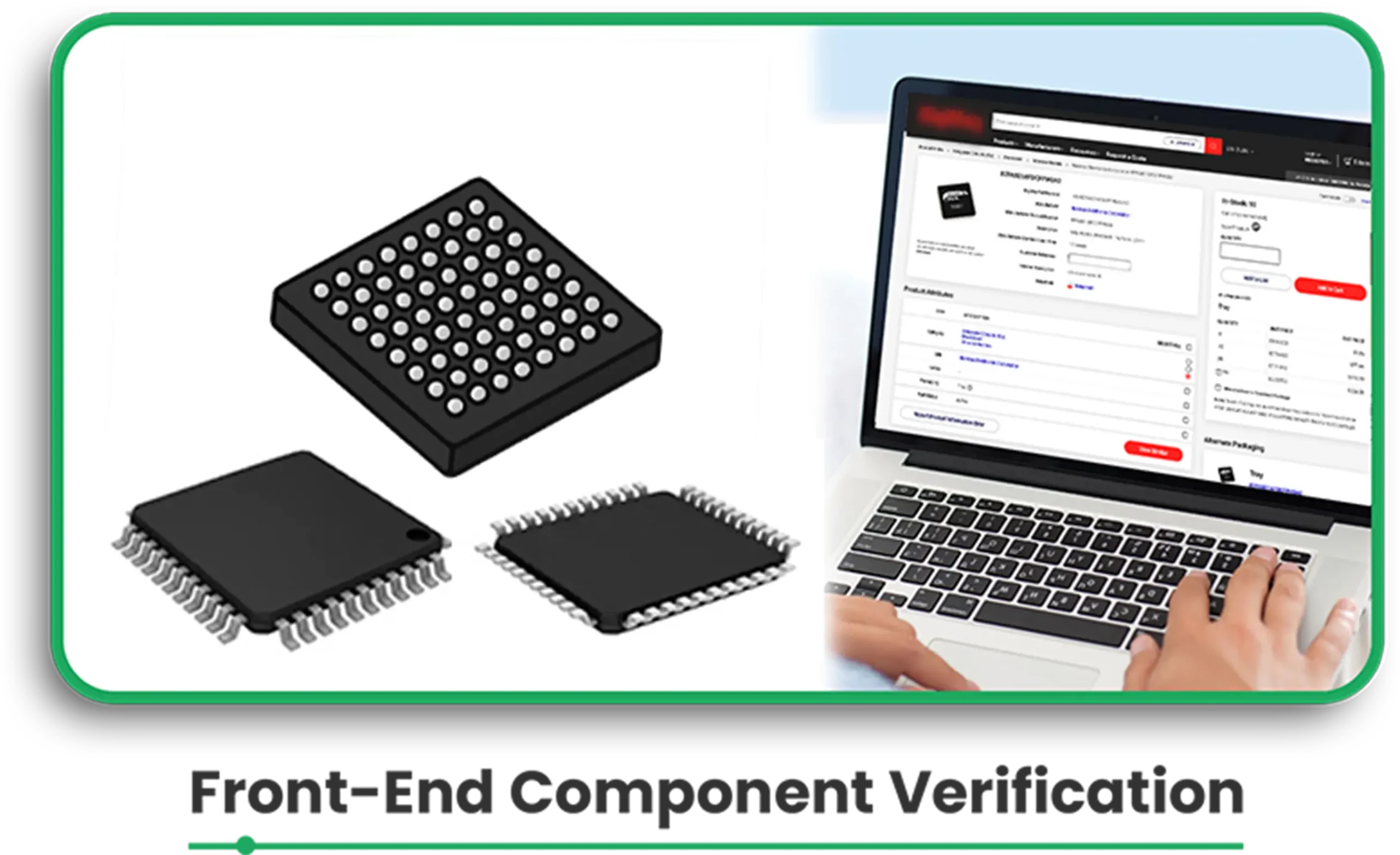
Step 4: Front-End Component Verification
For mounting, the correct placement, polarity, and type of package to be used against the PCB footprint are verified.
Special requirements for mounting are determined and corrected in this phase.
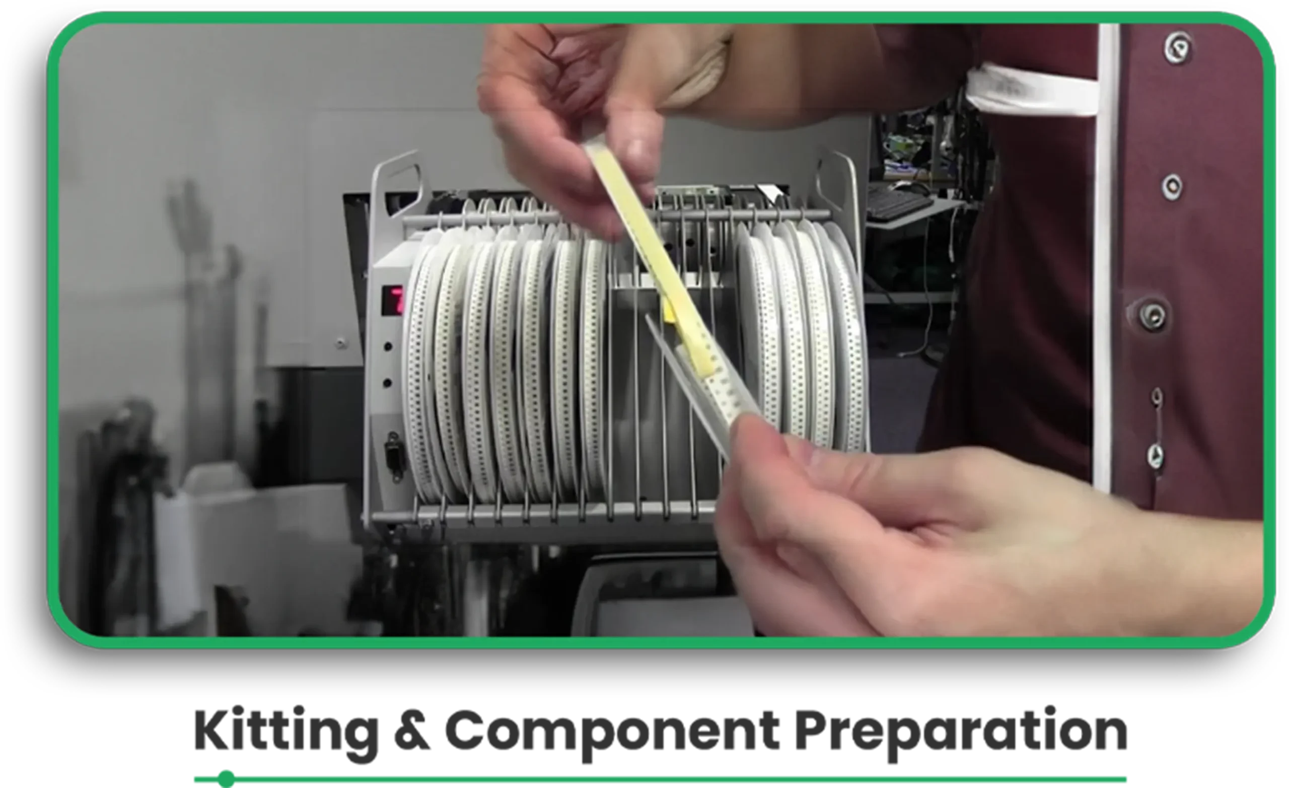
Step 5: Kitting and Component Preparation
Items are arranged in feeders for better organisation, ensuring that they are loaded into the pick-and-place machines efficiently.
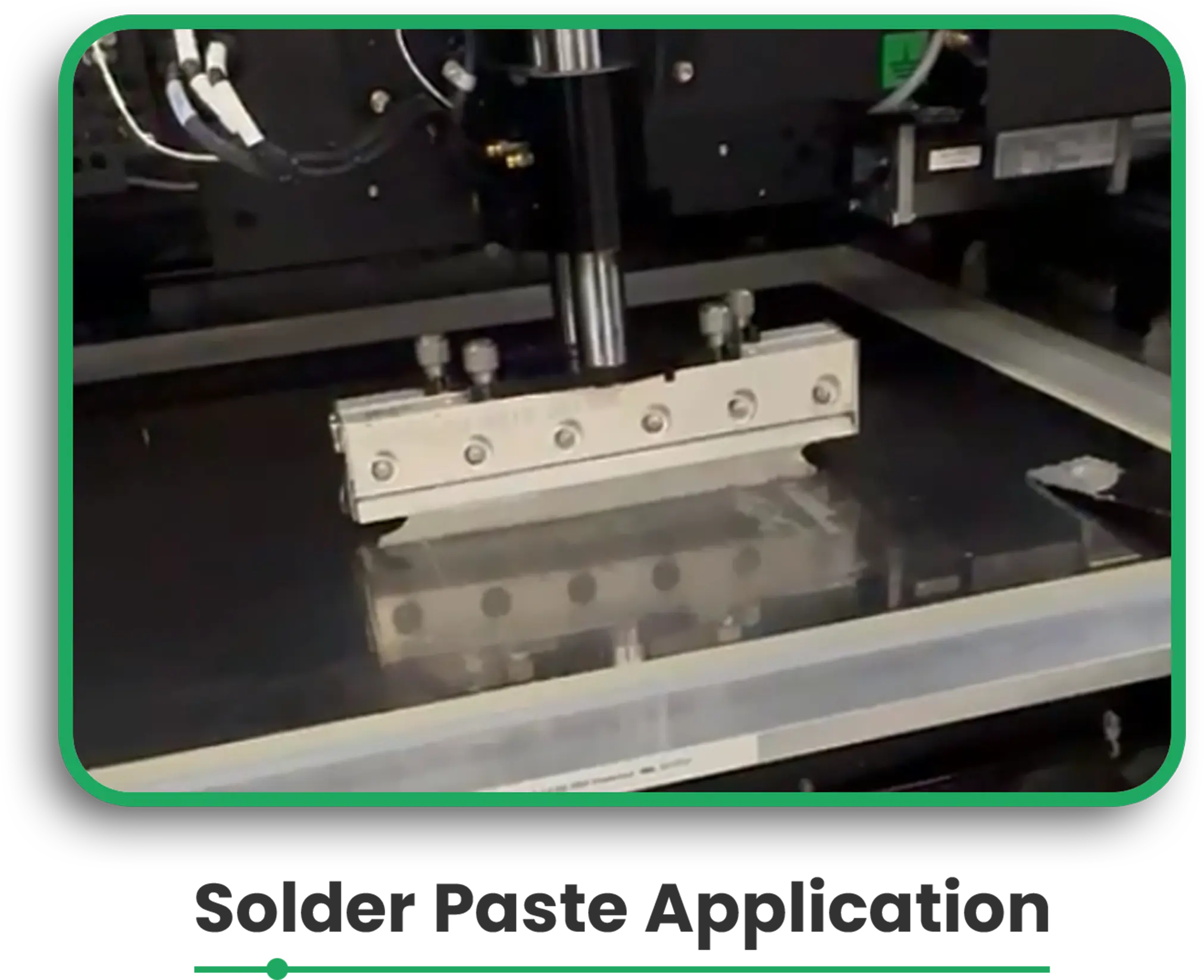
Step 6: Solder Paste Application
Until this phase, jetting or SMD stencil printing performs solder paste application to the PCB surface.
A solvent paste inspection (SPI) carries out the cure check to determine the paste’s adequacy for the ensuing procedure.
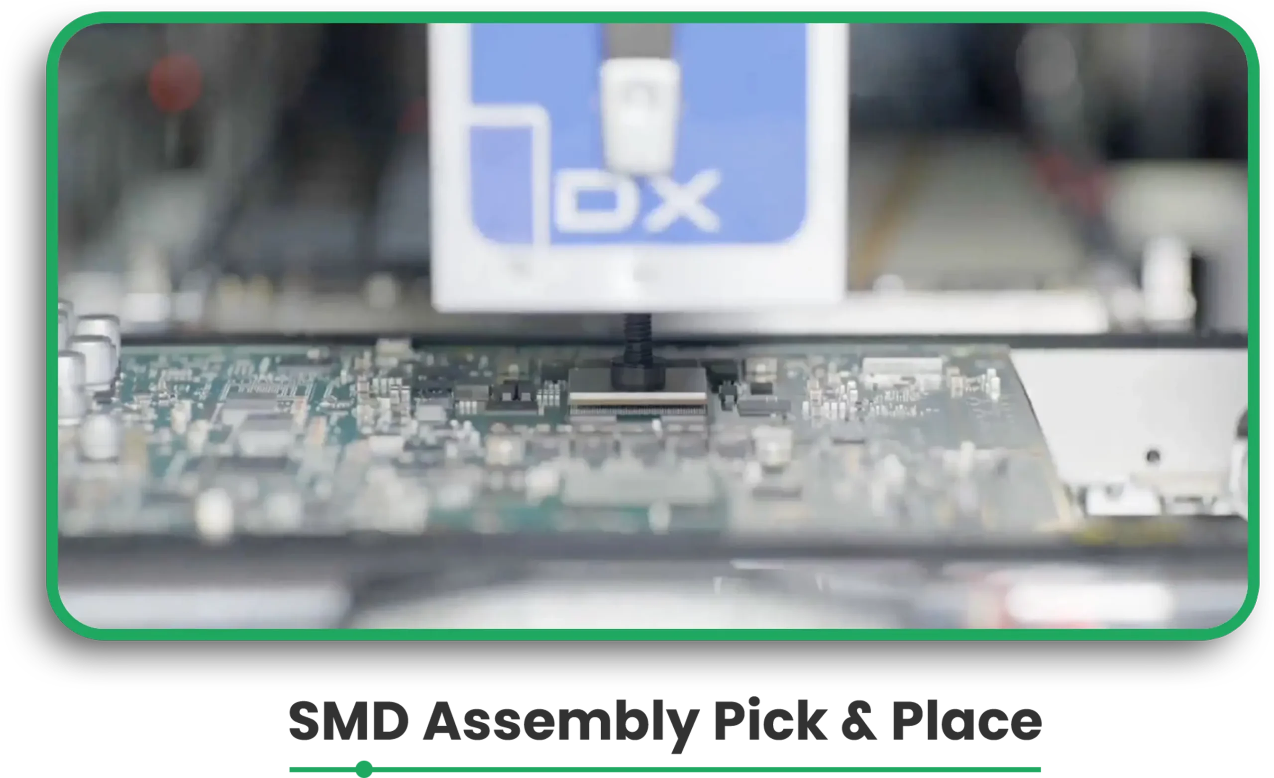
Step 7: SMD assembly: pick & place
SMD components are positioned on the board automatically by pick-and-place machines.
Thus, vision cameras inspect components for their sizes and angle position.
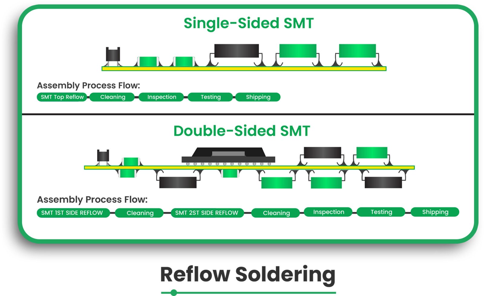
Step 8: Reflow Soldering
The board is passed over a reflow oven, which helps melt the solder paste into a solid state, creating an inlet electrical connection to the components and PCB pads.
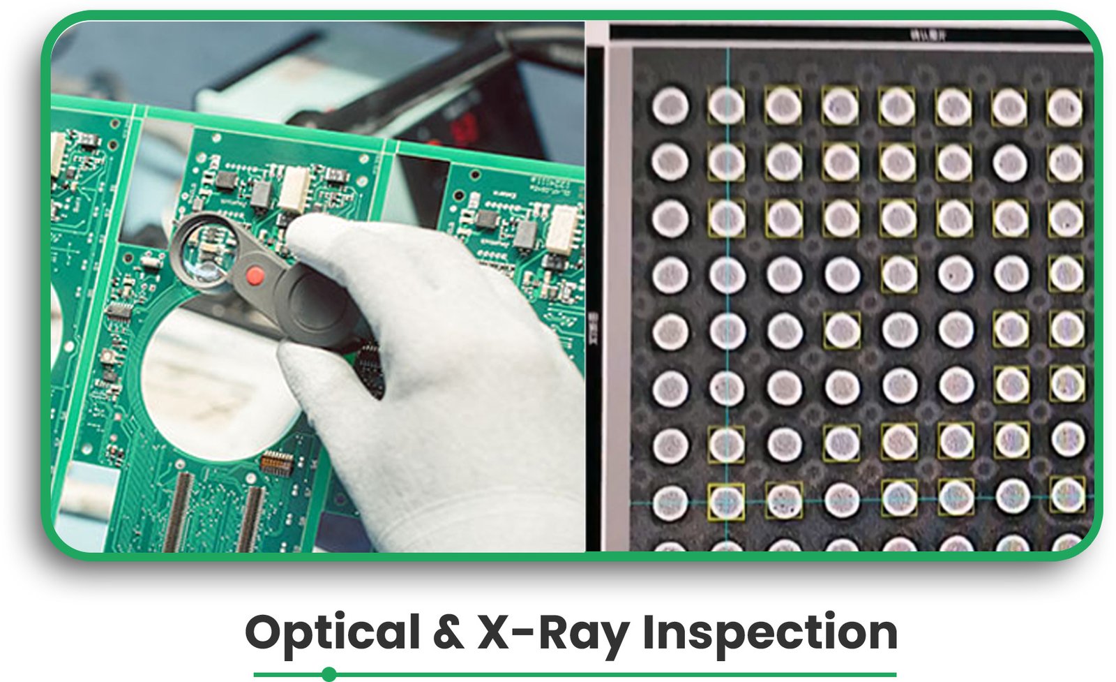
Step 9: Optical and X-Ray Inspection
PixPect optical inspection scans the board for defects and correlates the image with properly scanned sheets.
3D X-ray inspection can (with Nikon) detect concealed soldering connections and check the building quality of BGAs and LGAs components.
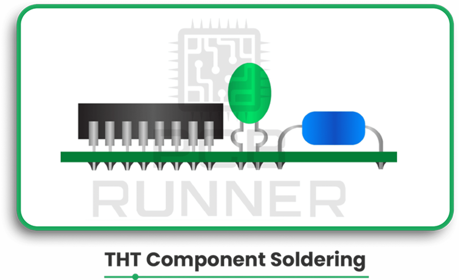
Step 10: THT Component Soldering
Through-hole ones are assembled by means of selective soldering machines or manual soldering techniques.
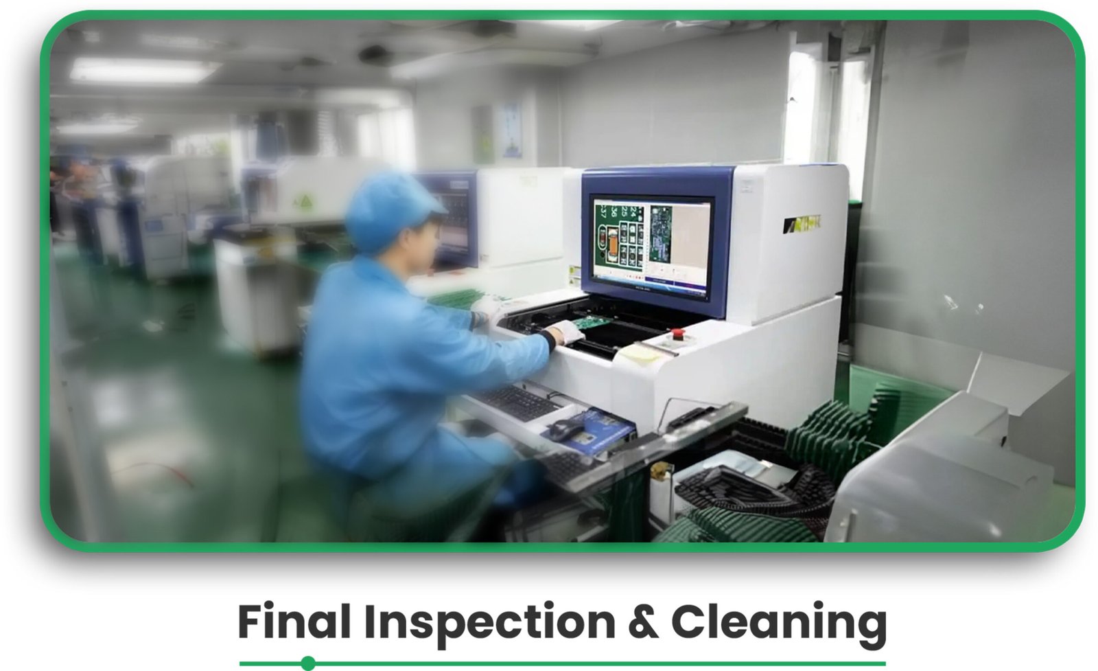
Step 11: Final inspection and cleaning
The final inspection should make sure that the assembled board is suitable for the design specifications.
Before shipping, the board is cleaned, and all defects are corrected.
Benefits and Application
Step by step understanding of the PCB assembly enables one to undertake the following actions:
- Enhancing Quality Control: By ensuring validation checks at many processes, the chances of committing errors are greatly minimized.
- Facilitate AI Methods: Integrated systems like automated component ordering and solder paste dispensing help to achieve quick turnarounds.
- Guarantee Component Fitting: Employing tools like PCBA Visualizer guarantees that components are placed and fit in accordance with the PCB’s design.
By following the above guidelines, accurate, high-quality PCBs are produced with shorter lead times, making it an essential resource for PC board manufacturers seeking efficiency in production.
Expert Insights:
“The following information is mentioned in the PCB Design Tutorial by David L. Jones.”
Many people start designing a PCB by placing all the components where they think they’ll fit best right away. While this approach might work for simple circuits, it’s not ideal for more complex designs with hundreds of components and multiple functional blocks.
The main reason is that you can quickly run out of “routing space,” which is the space needed to lay down all the tracks (connections). If you fix the positions of all components first and then try to connect them, you may find yourself stuck and unable to route some connections. On the other hand, if you space the components too far apart, you may end up with a large board that wastes space and increases PCB board manufacturing costs.
An inexperienced designer’s board often has evenly spaced components but messy tracks and vias (holes for connections) crisscrossing all over. This kind of design might work, but it’s inefficient, unattractive, and more expensive to produce.
The best way to start is by placing all the components on the screen first. If you’re using a schematic design tool, you can import the design into your PCB program to automatically place the components. If you’re only using a PCB program, you’ll need to select components from the library and place them manually.
Once all the components are on the screen, you can assess whether they’ll fit within the size and shape of your board. If the fit is tight, you’ll need to position the components carefully to save space and keep the routing efficient.
If you have plenty of space, you can be more flexible with your layout. However, if the components don’t fit at all, you’ll need to revisit your design and adjust.
FAQs
What files do I need for PCB assembly?
To ensure smooth printed circuit assembly, you need to upload the bare board data, BOM (Bill of Materials), and CPL (Component Placement List).
What is the purpose of solder paste inspection (SPI)?
SPI ensures that the correct amount of solder paste is applied to the PCB pads, which is critical for proper soldering and component attachment.
How does the pick-and-place machine work?
The pick-and-place machine automatically picks up SMD components and places them onto the PCB, ensuring precise component placement.
What is selective soldering?
Selective soldering is a technique for attaching through-hole components to the PCB. It ensures precise solder joints without affecting nearby components.
Why is X-ray inspection necessary in PCB assembly?
X-ray inspection is essential for checking hidden solder joints, particularly for difficult-to-inspect components like BGAs (Ball Grid Arrays) and LGAs (Land Grid Arrays).
Conclusion
The PCB assembly process involves a series of well-coordinated steps that ensure the final product is functional and high-quality. From design verification to component sourcing and final inspection, every phase plays a vital role in producing reliable PCBs.
By understanding this comprehensive process, both engineers and PC board manufacturers can make informed decisions that lead to faster production times and more cost-effective solutions for prototypes and small series production.

