Objective
To help engineers and buyers understand what actually drives PCB Material Selection, so board specs match the application instead of defaulting to whatever the fabricator has on the shelf.
Key Takeaways
- PCB Material Selection depends on electrical requirements first, cost second, not the other way round
- Dielectric constant and loss tangent decide whether a Multilayer PCB will perform at high frequency
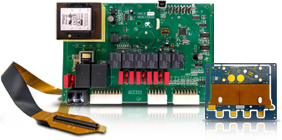
- Flex and Rigid Flex PCB builds need different material considerations than standard rigid boards
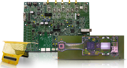
- High-Density Interconnects (HDI) PCBs demand dielectrics that support laser-drilled microvias reliably
- Getting material selection wrong shows up as signal loss, delamination, or thermal failure, usually after the board is already in the field
A customer once specced a high-speed board on standard FR-4 because it was the cheapest option on the quote sheet. The design passed simulation. It failed in the lab, with signal loss high enough to miss the data rate target by a wide margin. The circuit wasn’t the problem. The substrate was never going to support that frequency, no matter how clean the layout was.
This is the pattern we see most often. Teams spend weeks optimising a schematic and then treat the base material as a checkbox at the end. But the dielectric under the copper decides how the signal actually behaves, how much heat the board sheds, and how long the finished product survives in the field.
PCB Material Selection should start with the electrical and thermal requirements of the application, not the price list. Dielectric constant, loss tangent, and Tg determine how a board performs under real conditions. Multilayer PCB, Flex and Rigid Flex PCB, and HDI builds each need different material trade-offs. Getting this wrong costs far more to fix after fabrication than before it.
What PCB Material Selection Actually Means
PCB Material Selection is the process of matching the substrate, laminate, and dielectric to the electrical, thermal, and mechanical demands of the finished board.
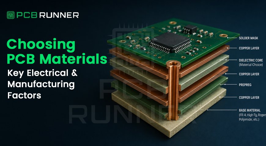
It’s not a single decision. It touches copper weight, resin system, reinforcement type, and the number of laminate combinations stacked through a Multilayer PCB. Each layer interacts with the ones next to it.
Get the electrical properties right but ignore manufacturability, and the board becomes expensive or impossible to fabricate reliably. Get manufacturability right but ignore the electrical side, and the board fails in the application it was built for.
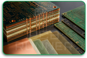 Key Electrical Factors
Dielectric constant (Dk): This determines how fast a signal travels through the material and how tightly you can control impedance. Standard FR-4 sits around 4.0 to 4.8. High-frequency laminates like Rogers RO4000 series run lower and more stable across frequency, which matters for RF and microwave designs.
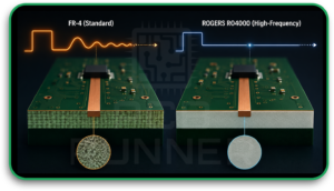
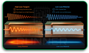
Loss tangent (Df): This measures how much signal energy the material absorbs as heat rather than passing along the trace. At low frequencies it barely matters. Above a few GHz, a high loss tangent will quietly eat your signal budget. Cyanate Ester and PTFE-based materials are chosen specifically for low Dk and low loss performance.
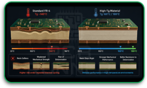
Glass transition temperature (Tg): Tg defines the point where the resin softens and mechanical properties start to degrade. Standard FR-4 runs around 140°C. High-reliability applications often specify 160°C or 180°C Tg material to handle repeated thermal cycling without delamination.
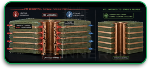
Thermal expansion (CTE): Mismatched CTE between the laminate and copper causes stress at plated through-holes during thermal cycling, eventually leading to cracked barrels. This becomes critical on thick multilayer stacks.
Key Manufacturing Factors
Electrical performance means nothing if the board can’t be built reliably.
Drill and lamination behaviour. Some high-performance dielectrics are harder to drill cleanly and need adjusted parameters to avoid smearing or resin recession. This affects hole wall quality and, eventually, plating reliability.
Layer count and press cycles. More layers mean more lamination cycles, and materials behave differently under repeated heat and pressure. A material that laminates predictably at four layers might shift or wrinkle at twelve.
Copper bond strength. Peel strength between copper and dielectric affects how well the board survives rework and thermal stress. This matters more on boards that will see field repairs or multiple reflow passes.
Availability and lead time. Speciality materials like Taconic or Nelco 6000 aren’t always stock items. Specifying them without checking lead time can turn a quick-turn project into a six-week wait.
Materials for Multilayer PCB Builds
A Multilayer PCB stacks several dielectric and copper layers together, and material choice affects the whole stack, not just one layer.
For general-purpose multilayer boards, standard or high-Tg FR-4 covers most commercial and industrial applications. For boards carrying high-speed digital signals, a hybrid stack mixing FR-4 with a low-loss material like Rogers RO4350 on critical layers balances cost against performance.
Halogen-free materials are increasingly specified for environmental compliance, particularly for customers shipping into markets with strict RoHS and halogen-free requirements across the UK and Europe.
Materials for Flex and Rigid Flex PCB and HDI PCBs
Flex and Rigid Flex PCB designs use polyimide as the base material almost universally. Polyimide bends repeatedly without cracking, which FR-4 simply can’t do. The trade-off is a higher dielectric constant and more moisture sensitivity than rigid FR-4, so designs need to account for that in impedance calculations.
High-Density Interconnects (HDI) PCBs bring their own material demands. Laser-drilled microvias need a dielectric that drills cleanly without excessive resin smear, and alternative HDI dielectrics are formulated specifically for this. Bond film thickness also needs tighter control, since HDI stacks often combine multiple lamination cycles to build up sequential layers.
If your project spans both flex sections and rigid sections, our Flex and Rigid Flex PCB capability page covers how we handle the transition zones where these material differences matter most.
What to Look for When Choosing a Material
Match Dk and Df to your actual frequency, not a generic “high-speed” label. A material chosen for 1GHz won’t necessarily hold up at 10GHz.
Confirm Tg against your thermal environment. Automotive and industrial applications usually need 170°C-plus, not standard 140°C FR-4.
Ask your fabricator about lamination history with the specific material. A material that’s new to a shop’s process carries more risk than one they’ve run for years.
Check material availability before finalising the design. A board specced around a hard-to-source laminate can sit in a queue waiting for stock.
Get PCB Material Selection reviewed alongside your stack-up, not after it’s finalised. Changing material after layout is locked in usually means reworking impedance and spacing too.
Cost Comparison
| Material Type | Typical Use Case | Relative Cost |
| Standard FR-4 (140°C Tg) | General commercial and industrial boards | Lowest |
| High-Tg FR-4 (170 to 180°C) | Higher thermal cycling, automotive, industrial | Moderate |
| Polyimide | Flex and Rigid Flex PCB builds | Moderate to High |
| Rogers RO4000 series / Cyanate Ester | RF, microwave, high-speed digital | High |
| PTFE-based laminates | Ultra-low loss, high-frequency applications | Highest |
Speciality materials cost more per panel, but a board built on the wrong material often costs more in rework, re-spins, and field failures than the material premium would have.
Conclusion
PCB Material Selection isn’t a line item to fill in after the schematic is done. It decides whether your board actually performs the way the design intended, and whether it survives the environment it’s built for.
If you’re speccing a new Multilayer PCB, a Flex and Rigid Flex PCB build, or an HDI project, contact PCB Runner for a material and stack-up review before you finalise the design. Call +44 203 2397011 or email sales@pcbrunner.com.
FAQs
Q. Do I need Rogers material for every high-speed design?
Not always. Many high-speed digital designs run fine on high-Tg FR-4 with careful stack-up and impedance control. Rogers and similar low-loss laminates earn their cost at higher frequencies, typically above a few GHz, or where insertion loss budgets are tight.
Q. Can you mix materials in the same Multilayer PCB?
Yes. Hybrid stacks combining FR-4 with a low-loss laminate on specific layers are common where only certain signals need the performance boost, and it keeps cost lower than an all-Rogers build.
Q. What material do you recommend for a flexible circuit that also needs a rigid section?
Polyimide for the flex sections is close to universal. The rigid sections typically pair with FR-4 or a compatible bonded material, and we help work out the transition zones during the design review.
Q. How do I know if my current board’s material choice was wrong?
Signal loss beyond spec, delamination during thermal cycling, or cracked via barrels after reflow all point back to material mismatch. Send us the stack-up and application details and we’ll tell you honestly if the material fits.
Q. Does material choice affect lead time?
Yes. Standard FR-4 is stocked and ships fast. Speciality laminates like Taconic, Nelco 6000, or certain Rogers grades may need to be sourced, which can add lead time to the project.