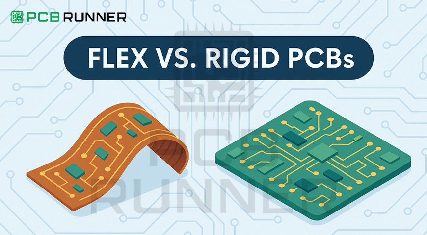
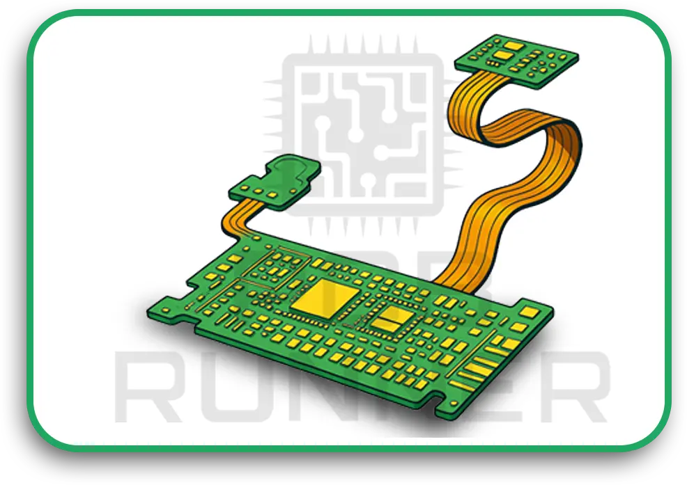
With the increase in the usage of modern day electronic devices, the need for complex, compact rigid-flex PCBs has gone exponentially higher. These types of PCBs have flexible substrates built into them which enable manufacturers to efficiently meet and adapt to various design requirements.
Creating flex circuit and rigid PCB assemblies involves advanced manufacturing techniques along with incorporating the right type of raw material. These factors combined make the entire process sophisticated and require a high level of accuracy and skill from the manufacturers.
Understanding Rigid-Flex PCB Components
The choice of materials is the most important step when constructing a rigid-flex PCB. The materials used in both the rigid and flexible sections of the PCB have to provide reliable performance throughout the set lifecycle of the product.
1. Substrates
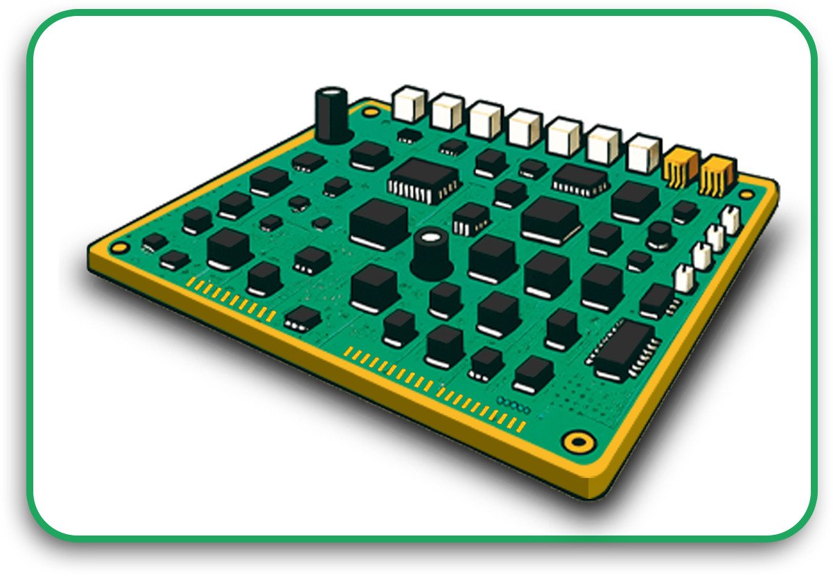
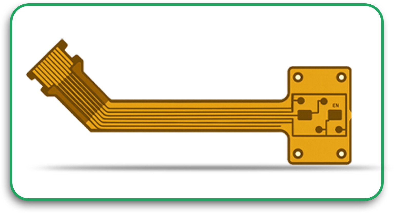
The rigid parts of the PCB are usually composed of FR-4, which is a strong epoxy resin and fiberglass compound that forms an integral part of the standard used PCB material. The flexible portions, however, depend on multi layer polyimide (PI) films which are thermally stable and flexible.
Polyimide (PI): PI films are well known for being mechanically robust during soldering processes and are capable of enduring extremely high temperatures.
Polyester (PET): Although Poly Targeting less warmth resistant than PI, PET proves to be extremely useful in instances where heavy soldering temperatures are avoided due to cost factors.
2. Materials of Conductors
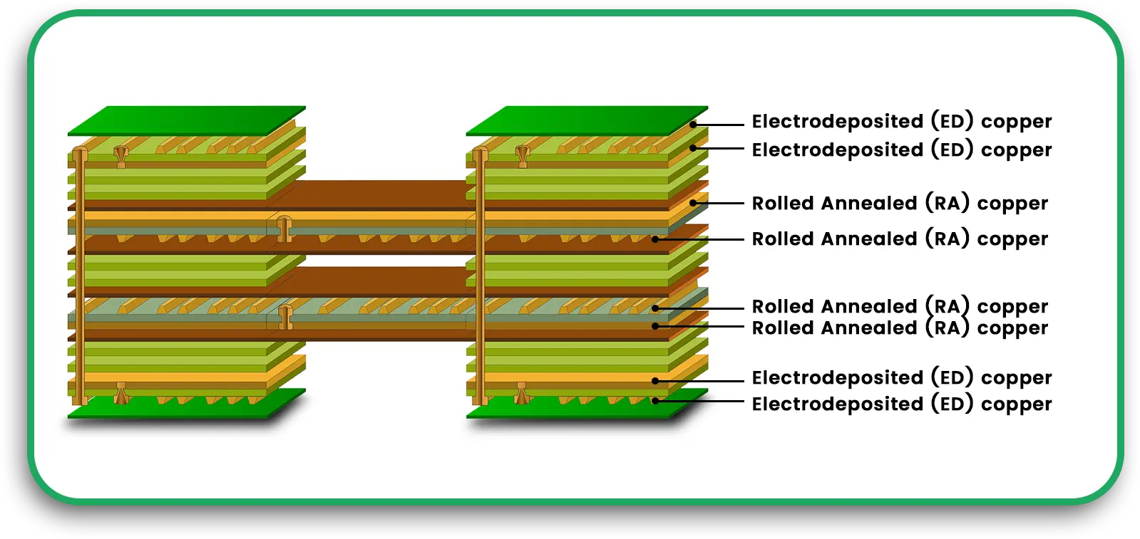
The conductive traces in rigid-flex PCBs are made of copper. Depending on the application, manufacturers may choose between:
Electrolytic Copper Foil: This is best used for high-current applications.
Rolled Annealed (RA) Copper: Enables the most intense bending and provides excellent strength and endurance.
3. Bonding and Hybridization Layers
In order to attach copper layers to the flexible substrates, epoxy and acrylic based bonds are widely used. Some latest techniques incorporate the use of adhesive-free laminates for increased flexibility and reliability.
Manufacturing Steps of Rigid-Flex PCBs
To create a rigid-flex PCB there are several important steps:
-
Layer Stack-Up Sequence Construction
The first step in the process of manufacturing is the design of the stack-up of the PCB. The stack-up outlines the configuration of conductive and non-conductive sections for both rigid and flexible parts.
The materials must meet the application’s electrical, thermal and mechanical requirements, and so engineers must plan ahead.
Simulation through CAD programs produces a more accurate design before being manufactured.
-
Adhesive Layer or Seed Deposit Application
A layer of acrylic or epoxy adhesive is placed on the base material. Rather, a seed copper layer can be sputtered over the substrate serving as a key for the plating.
-
Foil Copper Lamination
In the context of PCB manufacturing, copper foil is laminated onto the substrate through the use of thermal and mechanical techniques. Some processes in modern PCB manufacturing incorporate ductile, high-performing conductors through adhesiveless copper deposition.
-
Pictorial Cuts
This step consists of facilitating vias and pads that enable multilayer linkages. Depending on the design requirements, the drilling process may involve:
Mechanical Drilling: Use for boring larger openings.
Laser Drilling: Use in the creation of highly accurate micro vias.
Punching: Good for bulk manufacturing, albeit requires specialist equipment.
-
Completing the Circuit with Plating
After the holes are drilled, they are plated with copper to form electrical connections within the layers. To ensure the mechanical strength of flex and rigid PCB assemblies, the average plating thickness is 1 mil.
-
Applying Etch-Remove Covers
A layer of photosensitive etch-resist material is placed above the copper layers. The required circuit patterns are revealed and developed using photolithography.
-
Etching by Chemicals
The remaining traces of etch-resist are stripped off and the copper areas that were not covered previously are chemically etched to leave desired circuit traces.
-
Application of Coverlay or Covercoat
In order to safeguard the conductive paths, polyimide film coverlay layers are laminated to the flexible parts. In certain instances, a photo-imageable solder mask can be directly printed onto the board.
-
Mounting of Components
The assembly of surface mount and through hole components onto the rigid flex PCB is done by automatic pick and place machines.
Lead-free soldering: Helps comply with RoHS environmental regulations.
Reflow soldering: Allows for secure and reliable connections of components.
-
Quality Assurance and Testing
The rigid flex PCB is tested against a range of procedures to confirm functionality prior to shipment.
Electrical Testing: Testing circuits for continuity and isolation.
Mechanical Testing: Testing of flexibility and durability of the board.
Insights From Experts
Altium is well-known for offering innovative solutions in PCB design. They have noted the significance of innovation and accuracy in PCB production. A typical double sided flex circuit construction sequence features several specialized processes like seed coating and coverlay application. Notable methods for improving speed and quality for flex and rigid PCBs is laser drilling and adhesive-less copper deposition.
The research done by Altium suggests that modern changes in design tools and automation are making manual interventions less important in the production process. These changes allow producers to achieve better accuracy, lesser material wastage, and improve the reliability of the materials used for PCB boards, which in turn ensures better performance in critical applications.
Conclusion
Producing rigid-flex PCBs is a long and carefully executed process right from design to production involving the best materials, high-quality manufacturing processes, and rigorous testing. With improvements in the material used for PCBs and enhancement of the manufacturing process, the electronics industry is bound to become much more powerful and flexible in the times to come.
Through grasping each process step and employing expert knowledge, manufacturers can improve the production process of PCB assemblies, ensuring high-quality rigid flex solutions for various applications. Rigid-flex PCBs offer the world limitless possibilities for advanced electronics through wearables, automotive systems, and industrial millennium automation.
FAQs
What are rigid-flex PCBs used for?
Rigid-flex PCBs are popular in industries that need compact, light weight, and high performing electronics, like in wearable devices, aerospace, and industrial automation systems.
Which materials are commonly incorporated in rigid-flex PCBs?
FR-4 for the rigid sections and polyimide films for the flexible portions are the most used compounds, with copper serving as the material of choice for conductive traces.
In what ways do rigid-flex PCBs assist manufacturers?
They minimize the number of connectors and cables to be used, allowing for designs that are smaller in outline and more accurate in functioning.
What problems occur in the manufacturing of rigid-flex PCBs?
The process can be expensive, and maintaining alignment throughout the production process is a difficult and delicate process to achieve.
What advantages do polymer lamination foils provide?
They enhance flexibility, lower the mass, and increase the toughness of the PCB which is why they are best suited for modern day high technology applications.


