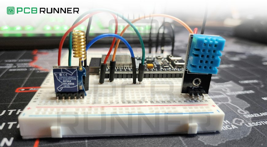
Both professionals and amateurs will find that the breadboard is one of the most vital tools for testing, tinkering, and constructing electronic circuits, all without the hassle of soldering the components together, making it invaluable for projects.
An electronics breadboard is a thin board that is usually rectangular and filled with a multitude of tiny holes. The holes are placed in an orderly manner and created in a grid-like fashion. Each microelectronic part, such as capacitors, resistors, transistors, microcontrollers, etc., can be joined together on these holes without the need for soldering.
As the last and final phase in the manufacturing of an electronics PCB, the breadboard serves as an excellent starting point for prototype testing. In this post, we will discuss why breadboards are so critical, how they compare to PCB fabrication, and what their role is in constructing a reliable PCB prototype before mass production.
Types of Breadboards
Each one of these breadboard boards is aimed to achieve a particular goal or purpose:
Solderless Breadboards: These are the most common ones and are employed for quick prototyping and educational purposes.
Soldered Breadboards: These are more flexible than full PCBs but have more permanent solder points.
Stripboards or Veroboards: The tracks of copper present on the board permit the designing of structured circuits.
Perfboards: They are like stripboards but have no copper tracks leading them, so wiring them is more labor-intensive.
Why Models Are Prototyped Using Breadboards?
Before breadboarding, engineers refine breadboards in order to polish their designs, and once they are happy, they move on to PCB fabrication. Here are some benefits of breadboards:
1. It’s user-friendly
The most well-known positive aspect of using a breadboard is that no soldering is needed. It simplifies the process of constructing, changing, and diagnosing circuits while preparing a PCB prototype. Components can be replaced or installed easily, eradicating the need for permanent adjustments.
2. Cheap to build
A breadboard is economical when trying out new circuit layouts. Unlike custom printed circuit boards, which mainly involve having them built and assembled, breadboards can be utilised endlessly.
3. Saving Time
Planning a PCB necessitates detailed work that can only be done with specific software, and there will be many design revisions as well. Engineers can skip these steps using breadboards and begin checking the functionality immediately. Once a circuit is successfully operating on a breadboard, it can be moved to a PCB prototype.
4. Experimentation or Debugging
Engineers can improve their designs by testing different configurations using breadboards. If a circuit is not working, components can be removed or moved to different positions literally in seconds.
5. Learning Made Easy
For novice electronic students or hobbyists, breadboards provide circuits with a great way to learn without high levels of skill in soldering or PCB design.
Breadboard Vs PCB Prototype: Determining the Switch Between the Two
Even though breadboards are helpful for early-stage prototyping, they are not perfect. Knowing when to shift to a PCB prototype is fundamental for the successful completion of a project.
When Should a Breadboard Be Used
- When conducting tests on simple circuits onl,y a few components are available.
- When creating circuits that operate in the low-frequency region (precise layouts are required for high-frequency circuits).
- When undertaking many projects that need to be altered often.
- When Should a PCB Prototype be Used
- When the circuit design has been confirmed and tested.
- When high-frequency signals and compact packing of circuit design need to be implemented.
- When a long lifespan and increased durability are needed.
Using PCB fabrication techniques, a printed circuit board can be made out of a successfully tested circuit that has been put on a breadboard. The design is now more compact, reliable, and professional.
Shifting Steps from a Breadboard to PCB
Moving from an electronics breadboard to a PCB prototype requires a few steps:
1. Build the Circuit Using PCB Software
For the circuit’s breadboard setup, engineers use standard PCB design software products that allow for intricate placement of each piece and can be optimised for power management.
2. Translate the Breadboard Layout into a PCB Schematic
An appropriate PCB schematic is drawn to describe the breadboard setup that specifies the connecting components.
3. Fine Tune the PCB Layout
Achieving power distribution effectiveness, controlling interference, and safeguarding signal integrity require planners to be cautious during the layout steps of PCB fabrication.
4. Production of the PCB Prototype
FR4, a fiberglass-reinforced epoxy, is used to fabricate a PCB prototype with conductive copper traces that replace the breadboard’s flexible connections.
5. Testing and Assembly
The final step is testing the manufactured PCB to ensure the components were soldered correctly and functioning as expected against the design from the breadboard.
Uses of Breadboards in Electronics
Breadboards serve a wide range of functions within the electronics field, in industries, and as educational teaching aids.
1. Development of Consumer Electronics
Businesses working on the next generation of consumer electronics utilise breadboards to test their original ideas before proceeding with PCB fabrication.
2. Automation in Industries
Engineers working on automation processes use a breadboard for rapid prototyping validations before developing the industry-standard custom printed circuit board.
3. Smart Devices and their Accessories
Most of the IoT devices started out with breadboard prototypes supported before it is transformed into compact PCBs.
4. Robotics and Embedded Systems Development
Breadboards are very common in robotics and embedded systems development projects for easier prototyping of motor controllers, sensors, and microprocessors.
5. Colleges And Universities
Universities and polytechnic colleges use breadboards in constructing and deconstructing circuits as a basic building block toward more advanced concepts in electronics and circuit design.
Prototyping and PCB fabrication
Prototyping and PCB fabrication are expected to evolve continuously with refinement and innovation. The following are a few of the newer ones:
- AI Assisting PCB Design: AI programs are now enabling engineers to automatically optimise circuit layouts for their convenience.
- Flexible PCBs—This innovation makes embedding circuits into surfaces with curves possible, creating more opportunities for wearables and medical gadgets.
- 3D Prototyping—The use of 3D printed circuit boards is rising as they reduce the time required to develop the final product.
- Software in the Cloud—More engineers are employing cloud-based professional PCB CAD tools for collaborative work on circuit designs.
Expert Insights
This novice study analyzes the methods used by children (ages 15–16) to cope with layout design principles and circuitry concepts that are fundamental to electrical engineering with the use of two available educational circuitry toolkits: paper circuits and solderless breadboards. Paper-based prototyping kits are indicative of a modern movement that seeks to integrate new materials and methods incorporating art within traditional STEM fields. Following up on the prior work on the use of non-conventional toolkits to teach electrical engineering concepts and basic circuitry concepts that include current flow, polarity, and connections, this study explores the affordances in materials as well as the design choices within the kits that account for advanced circuitry layout design principles that include space allocation and placement of electronic components alongside routing.
Results support that learning of layout design principles of printed circuit boards (PCBs) is more pronounced with paper circuits than with other tools, with large effect sizes reported. This study sheds light on the fact that the materials of educational toolkits have been designed in such a way that they suggest specific body and material-based patterns of activity, which engage learners’ powerful ideas concerning circuitry and design principles in different ways. This investigation emphasizes the fact that some toolkits, especially the non-conventional ones, have material affordances that make them more effective for some lessons.
Conclusion
Breadboards are essential tools for electronics prototyping. They enable engineers to dynamically develop and test circuit designs before constructing a custom printed circuit board.
Electronics breadboards are great for testing a circuit, but switching to a PCB prototype allows for a sturdier, more cost-effective, and more efficient end product that can be manufactured on a larger scale.
If you wish to develop your breadboard design further into professional PCB fabrication, PCB Runners is ready to assist you with your specific needs. Contact us to discover how we can turn your prototype into a functional custom PCB.
Frequently Asked Questions
What is the most notable benefit of using a breadboard?
Unlike traditional methods, breadboards allow users to easily construct and modify circuits without needing to solder, which makes them useful for testing and educational purposes.
Can you perform a test on a high-frequency circuit with a breadboard?
Testing high-frequency circuits is not very efficient on breadboards because of the chances of signal interference and stray capacitance. These issues are better dealt with in a PCB prototype.
How fast can one go from a breadboard to a PCB prototype?
It also could take anywhere from a few weeks to a few months, depending on the intricacy of the design, to go from straightforward design to the fabrication and assembly of your PCB.