PCB assembly is one of the most important stages in bringing an electronic product to life. PCB fabrication creates the bare circuit board, but PCB assembly places and sells the electronic components that make the product work. For OEMs, this stage carries serious responsibility. A wrong component, poor solder joint, weak process control, incomplete BOM, or missing test requirement can delay production or create failures in the field. At small volumes, these problems are frustrating. At production volumes, they become expensive very quickly.
This guide explains PCB assembly for OEM manufacturers. It covers assembly types, turnkey options, process stages, IPC standards, DFM and DFA, required files, testing, RoHS and REACH compliance, prototype validation, rigid-flex assembly, lead time factors, and how to choose the right PCB assembly partner in the UK and Europe.
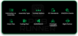
Key Takeaways
- PCB assembly is not the same as PCB fabrication.
- Assembly type affects cost, lead time, and quality.
- Turnkey, partial turnkey, and consigned assembly suit different OEM needs.
- IPC standards help define acceptable assembly quality.
- DFM and DFA checks prevent expensive production delays.
- Clean files reduce quoting, programming, sourcing, and assembly errors.
- Testing requirements should be discussed before production starts.
- RoHS and REACH compliance affect the full OEM supply chain.
- Prototype assembly helps validate the design before volume production.
- The right assembly partner can reduce risk, delays, rework, and field failures.
What Is PCB Assembly and Why Does It Matter for OEMs
PCB fabrication makes the bare board. PCB assembly puts the components on it.
For OEMs, assembly is where most of the product risk lives. A bad solder joint on one component can fail in the field. A wrong component in one location can damage the product. A missing process note can slow production. A poor inspection plan can allow defects to move forward.
OEMs depend on consistent and repeatable assembly. Not only for the first batch, but for every batch after that. This reliability comes from choosing the right assembly process, the right component sourcing method, the right IPC standard, and the right assembly partner from the start.
PCB assembly matters because it affects product quality, delivery timelines, compliance, warranty risk, and customer trust. A well-assembled board helps the product work as intended. A poorly assembled board can create intermittent faults that are difficult to find and costly to fix.
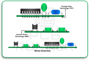
Types of PCB Assembly: SMT, THT, and Mixed Assembly
There are three common types of PCB assembly: SMT, THT, and mixed assembly. The right choice depends on the product design, component type, mechanical strength needs, production volume, and cost target.
SMT, or Surface Mount Technology, places components directly onto the board surface. No through-holes are needed for most SMT components. This method is fast, automated, and widely used in modern electronics. Compact consumer products, industrial electronics, communication boards, medical devices, and control systems commonly use SMT assembly.
THT, or Through-Hole Technology, uses components with leads that pass through drilled holes in the PCB. These leads are soldered on the opposite side of the board. THT is often used for connectors, large capacitors, terminals, power components, transformers, and parts that need stronger mechanical support.
Mixed assembly combines SMT and THT on the same board. Many OEM products use mixed assembly because compact SMT parts may be used alongside stronger through-hole connectors or power components. This is common in industrial controls, power supplies, automotive electronics, test equipment, and medical devices.
Knowing which assembly type your board needs before engaging a manufacturer helps avoid misquotes, process delays, fixture issues, and production surprises.
Full Turnkey vs Partial Turnkey vs Consigned Assembly: Which Is Right for Your OEM Project?
OEMs can usually choose between full turnkey, partial turnkey, and consigned PCB assembly. Each model has a different level of responsibility, cost control, sourcing effort, and risk.
Full turnkey assembly means the manufacturer handles everything. They source the components, procure the bare PCBs, assemble the boards, inspect them, and complete the agreed testing. The OEM sends the required files and receives finished boards. This option is useful when the OEM wants one clear point of responsibility.
Partial turnkey assembly means the OEM supplies some components, while the manufacturer sources the rest. This is common when the OEM already has controlled stock, approved suppliers, custom parts, programmed devices, or critical components that must come from a specific source.
Consigned assembly means the OEM supplies all components and usually the bare PCBs as well. The assembly house provides labour, equipment, process control, and inspection. This may reduce the assembler’s quoted cost, but the OEM still carries sourcing, kitting, logistics, shortage, part quality, and attrition risk.
For many OEMs, full turnkey assembly reduces sourcing work and gives one supplier clear responsibility for procurement, assembly, and delivery. Partial turnkey or consigned assembly may be better when the OEM has approved vendors, existing inventory, controlled components, or strict purchasing agreements.
The right choice depends on control, timeline, supply chain risk, cost target, and how much internal sourcing support the OEM already has.
Key Stages of the PCB Assembly Process
The PCB assembly process includes several controlled stages. Each stage affects the final quality of the assembled board. A good assembly partner not only places components. They review the files, check the BOM, confirm parts, prepare the line, control soldering, inspect defects, and test the board based on project requirements.
For OEMs, understanding these stages helps improve communication with the assembly house. It also helps avoid delays caused by incomplete documentation, missing parts, unclear assembly notes, or late changes.
BOM Review and Component Procurement
The Bill of Materials is reviewed before procurement and assembly begin. The BOM should list every component with manufacturer part number, reference designator, value, package type, quantity, tolerance, voltage rating, and approved alternates where possible.
During BOM review, the assembly partner checks component availability, lifecycle status, package compatibility, moisture sensitivity, RoHS compliance, and possible sourcing risks. Long-lead parts, obsolete components, and restricted supply items should be flagged early.
Approved substitutes should be agreed upon before procurement begins. Skipping this step can lead to last-minute sourcing problems that delay the entire production run.
Kit Auditing Of Component Count For Assembly
Kit auditing is especially important for consigned and partial turnkey assembly. Before the job reaches the assembly line, the component kit should be checked against the BOM, placement file, and build quantity.
This confirms that the correct components, quantities, package types, approved alternates, and reels or trays are available. It also helps identify shortages before production starts.
OEMs should provide enough attrition parts for feeder loading, setup loss, damaged parts, mispicks, and inspection rejects. Low attrition parts consignments can stop assembly even when the main BOM appears complete.
For small or expensive components, attrition planning should be discussed early. For fine-pitch ICs, BGAs, connectors, and low-quantity custom parts, missing extras can cause serious delays.
Stencil Printing and Solder Paste Application
For SMT assembly, solder paste is applied to the PCB before components are placed. A stencil, cut to match the pad layout, is aligned over the board. Solder paste is pushed through the stencil apertures so each pad receives a controlled deposit.
Stencil printing is a critical process. Too much solder paste can cause bridges, solder balls, or shorts. Too little paste can create weak joints, open, or poor wetting.
Stencil thickness, aperture design, paste type, squeegee pressure, board support, and print alignment all affect solder quality. Dense boards, fine-pitch components, BGAs, QFNs, and small passives need especially careful paste control.
Pick And Place Process
After solder paste application, automated pick-and-place machines place SMT components onto the board. Components are picked from reels, trays, sticks, or tubes and placed onto the correct pads.
The machine uses X&Y placement data, package information, orientation, and reference designators. Correct programming is essential. A rotation error, wrong footprint, incorrect polarity, or misplaced part can create a board failure.
Pick-and-place accuracy matters more as components become smaller and denser. Fine-pitch ICs, 0201 passives, BGAs, QFNs, and high-density boards need accurate data and a stable process setup.
Reflow And Wave Soldering
SMT boards go through a reflow oven after component placement. The oven follows a controlled temperature profile that melts the solder paste and forms permanent solder joints.
A proper reflow profile depends on board size, copper weight, component type, thermal mass, solder paste, and moisture-sensitive component requirements. Poor profiling can cause tombstoning, voids, cold joints, component damage, or insufficient wetting.
THT boards often use wave soldering or selective soldering. In wave soldering, the board passes over a wave of molten solder, which flows through plated holes and bonds component leads. Selective soldering is used when only certain through-hole areas need soldering, especially on mixed assembly boards.
Both reflow and wave soldering require process control. Temperature, dwell time, flux, conveyor speed, and board support all affect final quality.
AOI, X-Ray Inspection and Quality Control As Per IPC-A-610 and J-STD-001
Inspection and quality control should be built into the PCB assembly process. IPC-A-610 defines acceptability criteria for electronic assemblies, while J-STD-001 defines requirements for soldered electrical and electronic assemblies.
AOI, or Automated Optical Inspection, checks visible defects such as missing components, wrong polarity, skewed parts, lifted leads, solder bridges, insufficient solder, and incorrect placement.
X-ray inspection is used for hidden solder joints under components such as BGAs, QFNs, LGAs, and bottom-terminated devices. These joints cannot be inspected fully by normal visual methods.
Quality control should match the required IPC class, product risk, and end-use environment. A simple commercial board may not need the same level of inspection as a medical, aerospace, defence, or safety-critical assembly.
Defects caught early cost less to fix than defects found after the final product build, shipment, or field use.
IPC Class 2 and Class 3: Understanding Assembly Standards for OEMs
IPC standards help define what acceptable solder joints, component placement, and assembly workmanship look like.
For most commercial and industrial applications, IPC Class 2 is the standard requirement because it focuses on reliable performance and longer service life. Many higher-quality OEM products are manufactured to this classification.
IPC Class 3 covers high-reliability electronic assemblies where failure may create serious consequences. This may include certain medical devices, aerospace systems, defence electronics, mission-critical industrial controls, and safety-related products.
Some OEMs or industries may refer to enhanced Class 3, Class 3A, or project-specific high-reliability requirements. These should be clearly defined in the purchase order, assembly drawing, inspection plan, or customer specification. They may include extra documentation, traceability, inspection records, testing, cleanliness requirements, or space/military addendum requirements.
OEMs must specify the required IPC class before production begins. Building to Class 2 when the product requires Class 3 can create serious reliability and liability risks.
The assembly partner should confirm what standard they build to, what inspection records they can provide, and whether their process supports the required class.
Importance of Design for Manufacturability (DFM) and Design for Assembly (DFA): Why OEMs Must Get This Right
DFM and DFA are two of the most important checks before PCB assembly begins.
DFM, or Design for Manufacturability, checks whether the bare PCB can be fabricated accurately and consistently. It reviews trace widths, spacing, drill sizes, stack-up, copper balance, solder mask, vias, impedance needs, and fabrication capability.
DFA, or Design for Assembly, checks whether the board can be assembled efficiently and reliably. It reviews component spacing, pad sizes, footprint accuracy, fiducial placement, polarity markings, board edge clearance, panelization, component height, and access for soldering and inspection.
OEMs who skip DFM and DFA often pay for it later. A footprint that is slightly wrong can create repeat solder defects. Missing fiducials can slow machine setup. Poor spacing can make inspection difficult. Bad panelization can increase cost and handling risk.
Fixing these issues before production is easier and cheaper than fixing them after tooling, procurement, and assembly setup have started.
PCB Runner works with OEMs to run DFM and DFA reviews before production commitment, helping reduce delays and avoid preventable assembly problems.
PCB Assembly Files OEMs Must Provide
Clean and complete files help the assembly partner quote accurately, program machines correctly, source components, inspect the boards, and avoid delays.
OEMs should provide Gerber files, which define copper layers, solder mask, silkscreen, paste layers, and other board features. These files are essential for PCB fabrication.
The BOM, or Bill of Materials, lists every component used in the assembly. It should include the manufacturer part number, reference designator, value, package, quantity, tolerance, voltage rating, and approved alternates where available.
X&Y placement data, also called centroid data, tells the pick-and-place machine the position and rotation of each component. Without this file, placement programming becomes slower and more error-prone.
Assembly drawings are also important. They show which components go on which side, connector orientation, polarity, mechanical notes, no-fit parts, special handling instructions, and assembly-specific requirements.
OEMs should also provide test instructions, programming files, IPC class requirements, coating requirements, cleaning requirements, approved substitute rules, revision history, and any customer-specific notes.
The assembly drawing should be treated as a core production document. If important notes are missing, the assembly house may not know how the product must be built.
Quality Testing Methods: AOI, X-Ray, ICT, and Functional Testing As Per IPC Classifications
Quality testing should match the board design, IPC class, product risk, and customer requirements. Not every board needs every test, but every OEM should agree on the test plan before assembly begins.
AOI checks visible assembly defects. It is useful for detecting missing components, wrong orientation, solder bridges, lifted leads, incorrect polarity, and visible placement errors.
X-ray inspection checks hidden solder joints under BGAs, QFNs, LGAs, and other bottom-terminated components. It can help find voiding, bridging, opens, misalignment, and hidden solder problems.
ICT, or In-Circuit Testing, checks accessible nets and components through test points or fixtures. It can detect opens, shorts, wrong values, polarity issues, and some component-level faults. ICT coverage depends on board design and test point access.
Functional testing powers the board and checks whether it works as intended. This may include firmware loading, communication testing, voltage checks, sensor validation, relay switching, display checks, or full product simulation.
For IPC Class 3 or high-reliability products, testing and inspection are usually more detailed. The OEM should define acceptance criteria, inspection level, documentation needs, and traceability requirements before production starts.
RoHS and REACH Compliance and Its Importance in OEM Supply Chains
RoHS and REACH compliance matter for OEMs selling products into the UK, Europe, and other regulated markets.
Under RoHS regulations, specific hazardous substances in electrical and electronic equipment are restricted. These include lead, mercury, cadmium, hexavalent chromium, PBB, PBDE, and certain phthalates.
REACH focuses on chemical safety and substances of very high concern across the supply chain. It can affect components, PCB materials, coatings, labels, adhesives, cables, and other product materials.
For OEMs, compliance is not only about the solder alloy. Every component in the BOM, the bare board, solder paste, surface finish, coating, and assembly process, may need a compliance review.
A reliable PCB assembly partner should help collect material declarations, confirm lead-free assembly requirements, flag compliance risks, and support documentation for regulated markets.
Non-compliance can block market access, delay shipments, create legal liability, and damage customer trust.
Prototype PCB Assembly vs Production PCB Assembly
Prototype PCB assembly and production PCB assembly serve different purposes.
The prototype stage is used to validate the design before full production. It helps OEMs check fit, function, solderability, component placement, firmware, thermal performance, testing, and early DFM or DFA problems.
Production assembly focuses on repeatability, yield, documentation, cost control, and consistent quality across larger volumes. Once a product moves into production, changes become more expensive and slower to manage.
Skipping prototype assembly to save time can create larger delays later. A prototype build can reveal issues before they are locked into a full production run.
Why Prototype Assembly Matters
Prototype assembly matters because it gives OEMs a real build to test before production investment increases. It helps confirm whether the board can be assembled correctly and whether the product works as designed.
It can reveal footprint errors, missing test points, poor component spacing, incorrect polarity markings, thermal issues, connector fit problems, and functional faults.
Benefits of Prototype Validation
Prototype validation reduces the risk of production failure. It gives the engineering team a chance to test the design under real conditions and make improvements before committing to larger volumes.
It also helps confirm test procedures, programming steps, assembly notes, component substitutions, and inspection needs.
A good prototype run can save weeks of rework during production.
Moving From Prototype To Production
Moving from prototype to production should be controlled. OEMs should review test results, update design files, confirm BOM changes, approve alternates, finalize assembly drawings, and lock the revision.
The assembly partner should also review yield, defect trends, process notes, and any special handling requirements found during prototype assembly.
A smooth production handover depends on clean documentation and clear communication.
Assembly for Rigid, Flex, Semi-Flex, and Rigid-Flex PCBs: How It Impacts Cost and Lead Time
Not every PCB assembly project has the same handling needs. A standard rigid PCB is usually easier to fixture, print, place, solder, and inspect. Flex, semi-flex, and rigid-flex assemblies need more care because the board can bend, move, or require special support during assembly.
| PCB Type | Differences And Uniqueness | Additional Setups And Fixtures | Cost Impact | Lead Time Impact |
| Rigid PCB | Stable board structure and standard handling | Standard panel support and assembly setup | Usually the lowest cost | Usually the shortest lead time |
| Flex PCB | Thin, bendable circuit that needs careful handling | Carrier panels, stiffeners, or temporary fixtures may be needed | Higher due to handling and fixture needs | Longer if custom support is required |
| Semi-Flex PCB | Rigid board with limited flexible areas | Controlled bend areas and careful support may be needed | Moderate to high, depending on design | Can increase due to inspection and handling |
| Rigid-Flex PCB | Combines rigid and flexible sections in one assembly | Custom fixtures, bend protection, and special handling are often needed | Often, the highest among these options | Longer due to fabrication and assembly complexity |
Rigid-flex and flex assemblies can reduce connectors, save space, and improve product packaging. However, they need early planning. Bend areas, component placement, stiffeners, panelization, carrier fixtures, soldering support, and inspection access should be reviewed before production.
If flex or rigid-flex requirements are shared late, the assembly partner may need extra setup time. This can increase cost and lead time.
What Factors Affect PCB Assembly Lead Times?
PCB assembly lead time depends on more than the number of boards required. Component sourcing, board complexity, assembly process, testing requirements, documentation, and production volume all affect delivery time.
A simple SMT prototype with available parts may be completed quickly. A complex mixed assembly with BGAs, press-fit connectors, programmed devices, special inspection, or long-lead components will take longer.
OEMs should discuss lead time early, especially when launch dates, customer commitments, or regulatory deadlines are involved.
Component Availability
Component availability is one of the biggest lead time factors. Long-lead components can delay the entire project.
Microcontrollers, power ICs, FPGAs, connectors, sensors, RF parts, and specialist packages should be checked early. If a part is short in availability, the OEM should consider approved alternate part numbers before procurement becomes urgent.
Not considering alternate part numbers for parts with supply issues can create avoidable delays. Alternate parts should be checked for electrical compatibility, footprint compatibility, temperature rating, lifecycle status, and approval requirements.
PCB Assembly Complexity
Assembly complexity affects setup, programming, inspection, and production time. Dense SMT layouts, double-sided assembly, mixed SMT and THT assembly, fine-pitch ICs, high component counts, and special soldering requirements all increase process time.
Small passive components, tight component spacing, heavy copper boards, thermal pads, and odd-form components can also increase assembly difficulty.
Complex boards need more review before production. This helps reduce rework and improve yield.
Certain components and assembly methods increase lead time because they need extra control.
BGAs usually require careful placement, reflow profiling, and X-ray inspection. FPGAs may need controlled handling, programming support, and thermal review. Press-fit components need controlled insertion force and suitable tooling.
BGA underfill adds process steps and curing time. It may be used where mechanical strength, vibration resistance, or thermal cycling performance is important.
No-clean flux assemblies may still require process review. Even when cleaning is not required, residue behavior, inspection needs, customer requirements, and reliability expectations should be confirmed.
Critical components should be identified early so the assembly process can be planned correctly.
Testing Requirements
Testing requirements can increase lead time, but they also reduce risk.
AOI, X-ray, ICT, flying probe, functional testing, firmware programming, burn-in, and customer-specific test fixtures all affect the schedule.
Functional testing can take longer when the board needs software, calibration, external equipment, communication checks, or product-level validation.
The earlier testing requirements are shared, the easier it is to plan production time, fixtures, programming, and inspection flow.
Production Volume
Production volume affects lead time in different ways.
Prototype builds are often faster when parts are available, but they may require more engineering support and manual review. Production builds need more planning, setup control, process repeatability, inspection planning, packaging, and documentation.
Larger volumes may also need phased deliveries, panel optimization, additional fixtures, or supplier scheduling.
OEMs should build realistic lead time into the product plan instead of assuming assembly starts immediately after files are sent.
How to Choose the Right PCB Assembly Partner in the UK and Europe
Choosing the right PCB assembly partner matters because the supplier becomes part of the OEM supply chain. The wrong partner can create delays, quality issues, sourcing problems, and communication gaps.
Look for IPC knowledge and clear quality processes. Ask which IPC class they support and whether they can provide inspection records, process documentation, and traceability where needed.
Check their experience with your product type. A manufacturer that builds simple consumer electronics may not be the right fit for high-reliability industrial, medical, automotive, aerospace, or defence electronics.
Ask how they handle component shortages. A good partner should have authorised distributor relationships, a substitute approval process, and clear communication around sourcing risks.
Review their support for DFM, DFA, testing, RoHS, REACH, prototypes, production scaling, and special assembly requirements such as BGAs, press-fit components, flex circuits, and rigid-flex assemblies.
For OEMs in the UK and Europe, supply chain communication, compliance documentation, shipping, lead time transparency, and engineering support are especially important.
PCB Runner helps OEMs match their assembly needs with suitable manufacturing partners based on product requirements, quality expectations, production volume, testing needs, and sourcing complexity.
Common PCB Assembly Mistakes OEMs Should Avoid
Many PCB assembly mistakes are avoidable. Most happen because information is missing, decisions are rushed, or the assembly partner is involved too late.
One common mistake is sending incomplete BOM files with missing part numbers, missing tolerances, or unclear approved alternates. This creates sourcing delays and increases the risk of wrong substitutions.
Another mistake is skipping DFM and DFA reviews to save time. Avoiding the DFA just to expedite the project can create repeat defects during assembly. Poor spacing, incorrect footprints, missing fiducials, bad panelization, and difficult solder access can slow production or reduce yield.
Low attrition parts consignments are also a problem. When OEMs supply exactly the required component count without extras, production may stop because feeder loading, setup loss, mispicks, or inspection rejects have not been considered.
OEMs should also avoid moving straight to full production without a prototype run. A prototype can catch design and assembly issues before they affect a larger order.
Another mistake is choosing a manufacturer on price alone without checking IPC knowledge, sourcing controls, inspection capability, or relevant product experience.
OEMs should also avoid sourcing components outside authorised channels just to cut costs. Counterfeit or poor-quality components can pass basic checks but fail later in the field.
Not considering alternate part numbers for parts with availability issues can also create delays. Approved alternates should be reviewed early, not after procurement fails.
Assembly drawings should not be treated as optional. Important notes about polarity, connector orientation, no-fit parts, special soldering, IPC class, cleaning rules, coating, testing, torque requirements, and customer-specific requirements should be clearly mentioned. The assembly house will consider the assembly drawing as a core production document.
Conclusion
PCB assembly is a critical stage in OEM product development. It affects reliability, compliance, cost, delivery time, and long-term product performance. The best results come from clear files, complete BOMs, early DFM and DFA review, realistic lead time planning, proper IPC class selection, controlled component sourcing, and a practical test strategy.
Prototype assembly should be used to validate the product before full production. Rigid, flex, semi-flex, and rigid-flex boards should be reviewed early because each assembly type affects cost, setup, handling, and lead time.
For OEMs in the UK and Europe, the right PCB assembly partner should offer more than basic placement and soldering. They should understand sourcing, compliance, IPC requirements, inspection, testing, documentation, and production scale-up.
PCB Runner helps OEMs streamline PCB assembly by connecting the right process, supplier capability, quality controls, and production support from the start.
FAQs
What Is The Difference Between PCB Fabrication And PCB Assembly?
PCB fabrication makes the bare circuit board. PCB assembly places and solder components onto the board so it can function as an electronic product.
What Does Full Turnkey PCB Assembly Mean?
Full turnkey PCB assembly means the manufacturer handles component sourcing, bare board procurement, assembly, inspection, and testing. The OEM supplies the design files and receives finished boards.
What Is The Difference Between Full Turnkey, Partial Turnkey, And Consigned Assembly?
In a full turnkey assembly, the manufacturer sources everything. With a partial turnkey assembly, the OEM supplies some components while the manufacturer procures the remaining parts. Under a consigned assembly model, the OEM provides all components and typically supplies the bare boards as well.
Why Is Kit Auditing Important Before PCB Assembly?
Kit auditing confirms that the correct components, quantities, package types, and approved alternates are available before assembly starts. It helps prevent line stoppages caused by missing or insufficient parts.
What IPC Class Do Most OEM Products Require?
Many commercial and industrial OEM products are built to IPC Class 2. High-reliability products may require IPC Class 3 or additional project-specific requirements. The correct class should be confirmed before production starts.
Why Does DFA Matter In PCB Assembly?
DFA helps confirm that the board can be assembled accurately and efficiently. It checks component spacing, footprints, fiducials, panelization, solder access, and other assembly-related details.
What Files Do OEMs Need To Provide For PCB Assembly?
OEMs usually need to provide Gerber files, a complete BOM, X&Y placement data, and assembly drawings. Test instructions, programming files, IPC class requirements, and special notes should also be shared when needed.
Why Is X-Ray Inspection Used In PCB Assembly?
X-ray inspection is used to inspect hidden solder joints under BGAs, QFNs, LGAs, and other bottom-terminated components. These joints cannot be fully inspected visually.
What Is The Difference Between Prototype PCB Assembly And Production PCB Assembly?
Prototype assembly validates the design before volume production. Production assembly focuses on repeatability, quality control, cost efficiency, and consistent results across larger quantities.
How Do Rigid-Flex PCBs Affect Assembly Cost And Lead Time?
Rigid-flex PCBs often need special handling, fixtures, bend protection, and more careful inspection. This can increase both cost and lead time compared with standard rigid PCB assembly.
What Affects PCB Assembly Lead Time The Most?
Component availability, board complexity, critical components, special assembly processes, testing requirements, documentation, and production volume all affect lead time.
Why Are RoHS And REACH Important For OEMs?
RoHS and REACH help ensure products meet hazardous substance and chemical safety requirements in regulated markets. OEMs must manage compliance across components, PCBs, materials, solder, and supply chain documentation.

