Objective
This guide explains how embedded components can support a better high-current PCB layout. It also shows where they help, where they create problems, and what designers need to check before moving into PCB manufacturing and assembly.
Key Takeaways
Embedded components can save space in crowded board designs.
They can also help shorten some support paths when used in the right places.
Still, they are not the main solution in a high-current PCB layout.
Good copper planning, thermal control, stackup design, and current path management still matter most.
The best results come from early review with the PCB manufacturer before release.

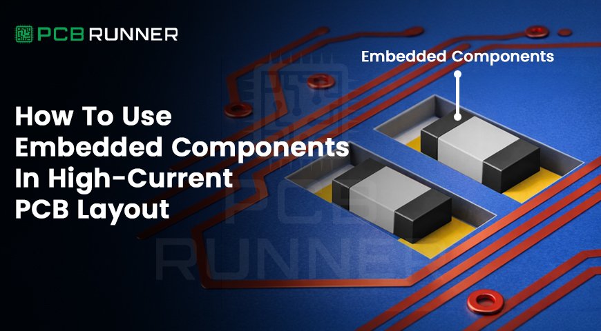
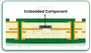
What Embedded Components Mean In High-Current PCB Layout
Embedded components are parts placed inside the board layers instead of only on the outer surface. These may include resistors, capacitors, inductors, and other small support parts. In simple words, they are built into the PCB stack rather than mounted on top of it.
In a high-current PCB layout, this idea can be useful because space runs out quickly. Power boards need wide traces, larger copper areas, safe spacing, and better heat control. Surface space gets crowded fast. When some support parts are moved inside the board, the outer layers become easier to use for routing and power devices.
That does not mean every board should use embedded parts. It only means they can help when a design needs to carry higher current and stay compact at the same time.
This is where practical PCB design matters. The goal is not to bury parts just to make the board look cleaner. The goal is to improve layout efficiency without creating new thermal or manufacturing problems.
Embedded Vs Surface Components
Before using embedded parts, it helps to compare them with standard surface-mounted components.
| Factor | Embedded Components | Surface Components |
| Placement | Inside PCB layers | On outer board surface |
| Space Saving | Saves surface area | Uses top or bottom space |
| Repairability | Very limited | Easier to replace or rework |
| Inspection | Harder to inspect | Easier to inspect |
| Manufacturing Complexity | Higher | Lower |
| Cost Impact | Usually higher | Usually lower |
| Thermal Access | Harder to monitor directly | Easier to observe and manage |
| Best Use | Small support circuits in dense layouts | Most common circuits and parts needing service |
This comparison makes one thing clear. Embedded parts are useful in the right situation, but they come with trade-offs. They are not automatically better than surface components. They are simply another design option.
Why Designers Use Them
Designers usually choose embedded components for a few practical reasons.
To Save Surface Space
Power boards often need wide traces, heavy copper, large copper pours, clearance zones, and thermal structures. That leaves less room for supporting components. Moving small parts inside the board can open up the surface for the features that matter more.
To Shorten Support Paths
Shorter paths can help reduce unwanted resistance and improve electrical performance in some sections of the board. This is especially useful in support areas near active devices.
To Protect Small Parts
A part inside the board is more protected from accidental contact, vibration, and surface damage. This can matter in industrial, automotive, and other demanding environments.
To Support Dense Layouts
Modern boards are often expected to do more in less space. Embedded parts can help when the design is compact but still needs solid electrical performance.
Where They Work Best
Embedded components do not make sense everywhere. In most high-current boards, they are more useful in support sections than in the main power path.
Good use cases include:
- decoupling structures placed close to active devices
- small passive networks in control areas
- support circuits near power stages
- dense mixed-function boards where surface space is limited
Less suitable use cases include:
- main current-carrying paths
- areas that already run hot
- designs that may need easy rework later
- projects with tight cost limits
- boards where inspection is critical
That is an important point. A high-current PCB layout is usually decided by copper width, copper thickness, layer structure, heat movement, and placement. Embedded parts can support that work, but they do not replace it.
When Not To Use Embedded Components
There are many cases where embedded components are not the right choice.
Do not use them just because the board looks crowded. That decision can create more problems than it solves.
They are usually a poor fit when the board may need repair or design changes later. A surface component can often be replaced. An embedded part usually cannot. If the project is still changing, keeping those parts accessible is safer.
They are also a poor choice in very hot sections of the board. High-current designs already deal with thermal stress. Hiding parts inside the stack can make heat harder to manage and harder to inspect.
Low-cost projects are another case where embedded parts may not make sense. They add process complexity, and that can increase manufacturing cost and reduce flexibility.
They also create risk when inspection matters a lot. If quality checks are a major part of the project, buried parts may create unnecessary difficulty.
In short, embedded components should be used only when they solve a real problem. If they only make the layout look neat on screen, they are probably not worth it.
Main Risks In High-Current Boards
This is where many designs fail. A compact layout may look efficient, but high current always brings heat, stress, and manufacturing pressure.
Heat Build-Up
High current creates heat. If a board is already running hard, internal parts may trap more heat than expected. That is harder to see and harder to fix later.
Harder Manufacturing
Embedded parts make the build more complex. They affect lamination, stackup planning, inspection, and sometimes yield. What looks simple in CAD may be difficult on the shop floor.
Limited Rework
Once a part is buried, it is no longer easy to replace. That means the design needs more confidence before release.
Current Crowding
Even when total copper looks acceptable, the current may still squeeze through narrow sections, bad transitions, or weak via structures. That can create local hot spots and reduce reliability.
Thermal Management In High Current PCB Layout
Thermal planning is one of the most important parts of a high-current PCB layout. This is true whether the board uses embedded components or not.
High current means more heat. That heat must move safely through the board and away from sensitive areas. If the thermal plan is weak, the layout will suffer no matter how clean it looks.
Copper thickness matters first. If the copper is too light, the board may not carry the load safely. Wide traces and large copper pours are also critical because they help spread current and reduce local heating.
Thermal vias are another important tool. They help move heat between layers and away from hot zones. In some designs, extra copper planes or metal-backed solutions may also be needed.
Part spacing matters too. Hot sections should not crowd sensitive control areas. Good separation improves both thermal behavior and electrical stability.
This is also why embedded components must be used carefully. They do not remove thermal problems. In some cases, they can make heat harder to track because the part is no longer visible on the surface.
A strong thermal plan should begin early. It should never be treated as a final check at the end of the layout process.
Design Rules That Matter Most
Here are the design rules that matter most when using embedded parts in a high-current PCB layout.
Start With The Current Path
Do not begin with the embedded parts. Begin with the power flow. First understand where current enters, where it splits, where it returns, and where heat is likely to build up.
Use The Right Copper Strategy
Embedded parts cannot make up for weak copper planning. High-current boards often need thicker copper, wider traces, or larger copper areas to stay safe and stable.
Keep Power And Control Areas Clear
Heavy-current sections and sensitive control areas should be separated whenever possible. This makes the layout easier to manage and helps reduce noise and thermal interaction.
Watch Via Design Closely
If current moves through vias, those vias must be planned carefully. Poor via design can create a bottleneck. Check via count, diameter, plating strength, and current sharing.
Embed Parts Only With A Clear Reason
Every embedded part should solve a real problem. It should free surface space, improve a support path, protect a small part, or support a dense design. If it has no clear purpose, keep it on the surface.
Review The Stackup Early
Embedded parts affect the stackup from the start. That is why early discussion with the PCB manufacturer matters. Waiting too long can create build problems later.
Plan For Inspection
A design is not complete unless it can be checked properly. Always ask how the buried areas will be inspected after fabrication and assembly.
Step-By-Step Design Process
A good process helps avoid design mistakes. Here is a simple way to approach embedded components in a high-current board.
Step 1: Define The Main Current Path
Find the full power path first. Identify entry points, exits, branches, return paths, and high-load zones.
Step 2: Mark The Heat Zones
Look at where heat is likely to build up. This gives you a better view of where embedded parts may create risk.
Step 3: Build The Copper Plan
Choose copper thickness, trace width, pours, and planes before thinking about compactness. Current capacity comes first.
Step 4: Separate Power And Control Sections
Keep noisy and hot zones away from more sensitive support circuits. This makes routing cleaner and improves reliability.
Step 5: Decide What Should Stay On The Surface
Parts that may need service, inspection, or thermal access should usually stay on the outside.
Step 6: Choose Embedded Parts Carefully
Only embed support parts that bring a clear layout benefit. Small passive parts are usually the safest candidates.
Step 7: Check Vias, Stackup, And Build Limits
Make sure the layer structure, via design, and board construction all support the final layout.
Step 8: Review With The Manufacturer Early
Before release, get design-for-manufacturing feedback. This helps catch issues that are easy to miss during layout work.
A Simple Planning Table
| Design Area | What To Check | Why It Matters |
| Current Path | Width, thickness, bottlenecks | Prevents overheating |
| Stackup | Layer use, spacing, embedded zones | Supports build quality |
| Thermal Plan | Vias, copper pours, heat spread | Controls temperature |
| Part Choice | Which parts to embed | Avoids pointless complexity |
| Manufacturing Review | DFM and assembly input | Reduces risk before release |
| Reliability | Repair limits, stress points | Improves long-term use |
This table is simple, but it covers the real decision points that matter in PCB design.
Common Mistakes To Avoid
One common mistake is treating embedded parts as the main solution. They are not. They are only one tool in a larger design strategy.
Another mistake is ignoring thermal reality. A compact board may still fail if heat is not managed well.
Some teams also forget manufacturing limits. A layout that looks smart in software may be difficult to fabricate at scale.
Inspection is another area where mistakes happen. If the board cannot be checked properly, risk goes up.
Finally, some layouts overcrowd the inner layers. Inner layers are not free storage space. They still need clean routing, spacing, and balance.
Conclusion
Embedded components can be a smart choice in a high-current PCB layout when they solve a real design problem. They can save surface space, support compact layouts, and improve placement in certain support sections. But they are not the foundation of a reliable power board.
The real foundation is still the same. Good copper planning. Clear current paths. Strong thermal control. Clean stackup decisions. Early manufacturing review.
The best approach is simple. Start with current flow. Follow the heat. Protect inspection. Then decide what should stay on the surface and what, if anything, should be embedded.
That kind of practical thinking leads to better boards and fewer surprises during manufacturing and assembly.
FAQs
1. What Are Embedded Components In A PCB?
Embedded components are parts placed inside the layers of a PCB instead of only on the outer surface. They are often small support parts such as resistors or capacitors.
2. Are Embedded Components Good For High-Current PCB Layout?
They can be useful in the right design, but they are not the main answer. High-current performance still depends on copper size, current path design, thermal planning, and stackup quality.
3. Do Embedded Components Help Save Space In PCB Design?
Yes, they can free up surface space by moving some support parts into the inner layers. This can help in dense board layouts.
4. Do Embedded Components Reduce Heat Problems?
Not by themselves. In some cases they may support a cleaner layout, but proper heat control still depends on copper, spacing, thermal vias, and overall board design.
5. Which Parts Are Usually Best To Embed?
Small passive support parts are usually the safest choice. Main power parts need much more caution because of heat, inspection, and repair concerns.
6. When Should Embedded Components Be Avoided?
They should usually be avoided in designs that need easy rework, tight cost control, simple inspection, or better thermal access.

