A macropad PCB is a miniaturized circuit board intended for personalized input devices that let users set macros, shortcuts, or hotkeys for a more efficient workflow. Custom slabs of a macropad PCB can significantly increase efficiency in gaming, video editing, and coding. The creation of a macropad PCB design necessitates appropriate printed circuit board design software, selection of solder mask material, and reputable PCB manufacturers for fabrication. Given the competition for high-density interconnect (HDI) technology, modern methods of assembling circuit boards result in easily fabricated and reliable macropods.
This blog will cover everything from designing the layout to doing the final assembly.
Step 1: Basics of a Macropad PCB
A macropad PCB acts as a small keyboard that has programmable keystrokes or buttons. A macropad can be compared to a keyboard, and it too has keys, albeit lesser in number, approximately 3-20, that are designed for certain operations.
Main Parts Of A Macropad PCB
- Microcontroller Unit (MCU) :The controller of a macropad that reads the key press.
- Switches: Mechanical or capacitive switches that detect the input.
- Diodes: Employed in the switch matrix for ghosting protection.
- Traces and Vias: Pathways that connect components electrically.
- USB Connector: The means through which the macropad interfaces with the computer.
- LEDs (Optional): Provides backlight or indicator function for a user interface.
Through learning these components, one is set to design an efficient and functional macropad PCB.
Step 2: Selection of Printed Circuit Board Design Software
- For macropad PCB design, you would need specialized printed circuit board design software with both schematic capture and edit layout functions. Some you may consider are:
- KiCad : It is free and open source that is widely used on custom PCBs
- Eagle: This is more sophisticated software with a rich components library.
- Altium Designer: It is top-of-the-range professional printed circuit board design software.
- EasyEDA: This is good for first-time users, and it is web-based.
Select the one that corresponds to your level of experience and approach to the project.
Step 3: Forming the Macropad Schematic
A schematic is a diagram which shows how components are linked together. This is how you draw it in your printed circuit board design software:
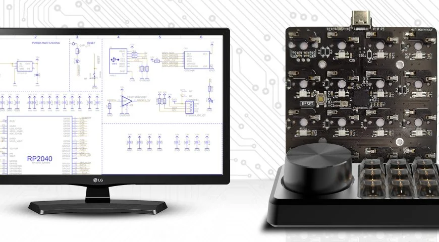
Place the Microcontroller: Popular candidates are ATmega32U4 or RP2040, which both can accept USB input.
- Add Switches: Decide and set the number of keys and how they will be aligned.
- Include Diodes: These avoid interference that can happen from a switch matrix.
- Draw Power and Ground Connections: These are essential to ensure good power distribution.
- Define the USB Interface: Choose a USB-C or Micro-USB socket.
After the schematic is done, conduct electrical checks before you proceed to the PCB layout.
Step 4: Designing the PCB Layout
1. Establish Board Sizes
You have to scale and contour your macropad PCB in relation to your case and key arrangement so you figure out its size.
2. Place the Components
- Traces should be as short and straight as possible to reduce signal degradation.
- Place diodes near switches to tidy up the layout.
- Adjust components for efficient soldering and assembly.
3. Route Traces and Vias
- Use interconnection techniques for compact designs – High-density interconnects (HDI).
- Trace gaps must be sufficient to avoid shorting between them.
- Deploy ground planes for lower noise and improved stability.
4. Choose Appropriate Solder Mask Material
The solder mask material is in charge of preventing the PCB from oxidizing and covering solder bridge accidents. Usual choices are:
Epoxy Liquid: It is cheap, but it can be brittle.
Liquid Photoimageable (LPI) Solder Mask – Capable of great precision.
Dry Film Solder Mask: Best for high-density interconnect PCBs.
Select a solder mask material that best meets production requirements.
Step 5: Getting Ready for PCB Manufacturing
These are the two additional tasks that need to be performed before sending the board to the PCB manufacturer:
- Execute a Design Rule Check (DRC) – Validate that there are no design infringements.
- Examine the Trace Width and Trace Spacing – How their values comply with the acceptable fabrication ones.
- Create Gerber Files – a must for PCB design fabrication.
Once you have completed verifying the design, send it to a reliable PCB board manufacturer for construction.
Step 6: Circuit Board Assembly
With the macropad PCB fabricated, you are now ready to assemble the circuit board (CBA). You can choose to:
- Solder Components by Hand – Ideal for hobbyists or small-volume production.
- Outsource to a PCB Assembly Contractor – Best for larger quantities.
Key Steps in Circuit Board Assembly:
- Solder Paste Application – For use with surface mount components.
- Component Placement – Brought in with the aid of pick-and-place robots or done manually with tweezers.
Soldering Reflow: Heats solder to install components.
- Soldering Through-Hole – Applicable to diodes and switches.
- Final Checks and Verification – Validates functionality of all the solder joints.
Step 7: Programming the Macropad
After the PCB is transferred, it needs some firmware to operate. Some of the more common choices are:
- QMK – Customizable for various uses.
- VIA Firmware – User-friendly software interface to configure keys.
- Arduino IDE – Friendly for use with simpler tasks.
Procedure to Flash the Firmware:
- Plug in the Macropad via USB to a computer.
- Get the needed Drivers Support for the microcontroller.
- Inject Firmware with QMK Toolbox or similar software.
Verify Functionality by pressing all the keys to check whether they work.
STEP 8: Final Examination and Problem Fixing
Running a test on a macropad PCB requires several steps. The first step is testing:
Basic Tests:
- Continuity Test – Checks if the traces have continuity.
- Keypress Test – Checks if the switches output as expected.
- USB Connection Test – Tests a device’s ability to communicate with the host computer.
Helpful Hints:
Registering issues? You may want to look for solder joints and diodes.
No USB connection? Check your firmware configuration and trace the wires.
If everything else is fine but the components are hot, then check the power trace and ground.
Final Thoughts
From schematic design to circuit board assembly and firmware flashing, all steps require thoughtful consideration when designing a macropad PCB. Using the appropriate printed circuit board design software, high-density interconnect methodologies, and reputable PCB suppliers will ensure that the macropod is robust and effective. It is indisputable that a thoughtfully designed macropod PCB improves productivity, creativity, or user experience, whether it is for gaming or macro-programmability.
Do You Have Any Questions About Macropad Fabrication?
Here at RUNNER PCB, we take pride in our quick turnaround time with any custom requests. Along with the high-quality solder mask material and advanced PCB fabrication techniques we offer, delivering reliable service is at the forefront of our business model. Reach out today to get started!
FAQs
1. What is Macropad PCB?
It is a small circuit board complete with programmable keys intended for custom shortcuts or macros.
2. Which material is most suitable for a solder mask on a Macropad PCB?
Liquid Photoimageable (LPI) Solder Mask is the best choice in terms of quality and endurance.
3. What steps are to be taken to flash a firmware into a Macropad PCB?
Custom key function firmware can be flashed using QMK, VIA, or Arduino IDE.
4. Is it possible to hand-solder Macropad PCB?
It’s possible, but it’s less reliable than using a circuit board assembly service.
5. Where can I order a Macropad PCB?
Professional PCB fabrication and assembly for custom macropad PCBs is offered by PCB Runners. Reach out to us today!

