Recently, there has been a significant introduction of enhanced features in consumer electronics—flexible displays. From curved televisions to foldable smartphones, the designs are sleek and offer some modern features.
Flexible Printed Circuit Boards (FPCBs) enable the core structure of these devices and their displays. In this blog, we’ll explore how flex and rigid PCB technologies are essential for modern, flexible displays and their benefits across industries.
What Are Flexible Printed Circuit Boards?
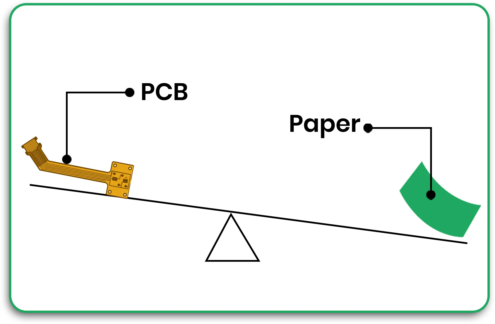
FPCBs, or flexible PCBs, are designed to bend without losing their electrical function. Unlike Traditional rigid PCBs, these are more modern and are crafted from substrates such as polyimide, which provide them with the needed shape.
Types of PCBs Used in Flexible Displays
Flex PCBs are ultra-flexible circuit boards used in devices that require folding, twisting, or curving features.
Rigid-Flex PCBs: The circuit board is made of a combination of flexible and rigid circuits. True to its name, it offers enhanced strength whilst maintaining adaptability.
Both types, as mentioned above, are widely termed compact and lightweight components.
The Importance of Flexible PCBs within Flexible Displays
A flexible display needs to have parts that are light in weight, compact, and effective. Conventional rigid PCBs cannot meet these specifications because of their inflexible structure. Flexible PCBs offer a solution because they have the following characteristics:
- Bendability: The feature necessary for smartphones and mobile wearables.
- Space Efficiency: FPCBs use less vertical space, making it possible for manufacturers to construct ultra-thin displays.
- Lightweight Structures: This feature is beneficial for portable devices such as tablets and fitness trackers.
- Durability: Flex circuits perform consistently over time, even after repeated cycles obending.
Key Materials Used in Flexible PCBs
The kind of materials selected for flexible PCBs for displays determines the performance and reliability of the PCB.
Substrate Material:
- Polyimide is the material of choice because of its flexibility and high thermal stability.
- Polyester is also used for cost-sensitive applications, although it has a lower resistance to thermals.
Conductor Material:
- Copper is widely used because of its good electrical conductivity.
- Copper foils can be laminated with the polyimide flexible substrate to produce robust circuit traces.
Adhesive Layers:
- Epoxy or acrylic adhesive serves as the conductive layer and the polyimide substrate adhesive.
Methods of Construction for Flexible PCBs
Building FPCBs aims to achieve flexible display capabilities, and the following procedures do it:
1. Cleaning and Preparing Substrate
The flexible substrate is cleaned and laminated with an adhesive layer and a protective coat.
2. Etching and Patterning
The Circuit patterns are created with Photolithography techniques, followed by excess copper removal through etching.
3. Application of External Circuitry
The multilayer integrated FPCB structure is constructed by laminating single circuits.
4. Plating and Drilling
Sequential plated through holes (Vias) are drilled for layering, and then electrical connections are plated to the Vias.
5. Quality Assurance and Testing
Flexible PCBs have high reliability and performance which comes from extensive testing as well as industry standard incorporation.
Usage of Flexible PCBs in Screens
The adoption of flex and rigid PCB technologies has remarkably increased, enabling their use in flex and bendable displays:
1. Smart Phones with Attachments
Flexible PCBs allow folding designs of displays as they bend around the corners seamlessly.
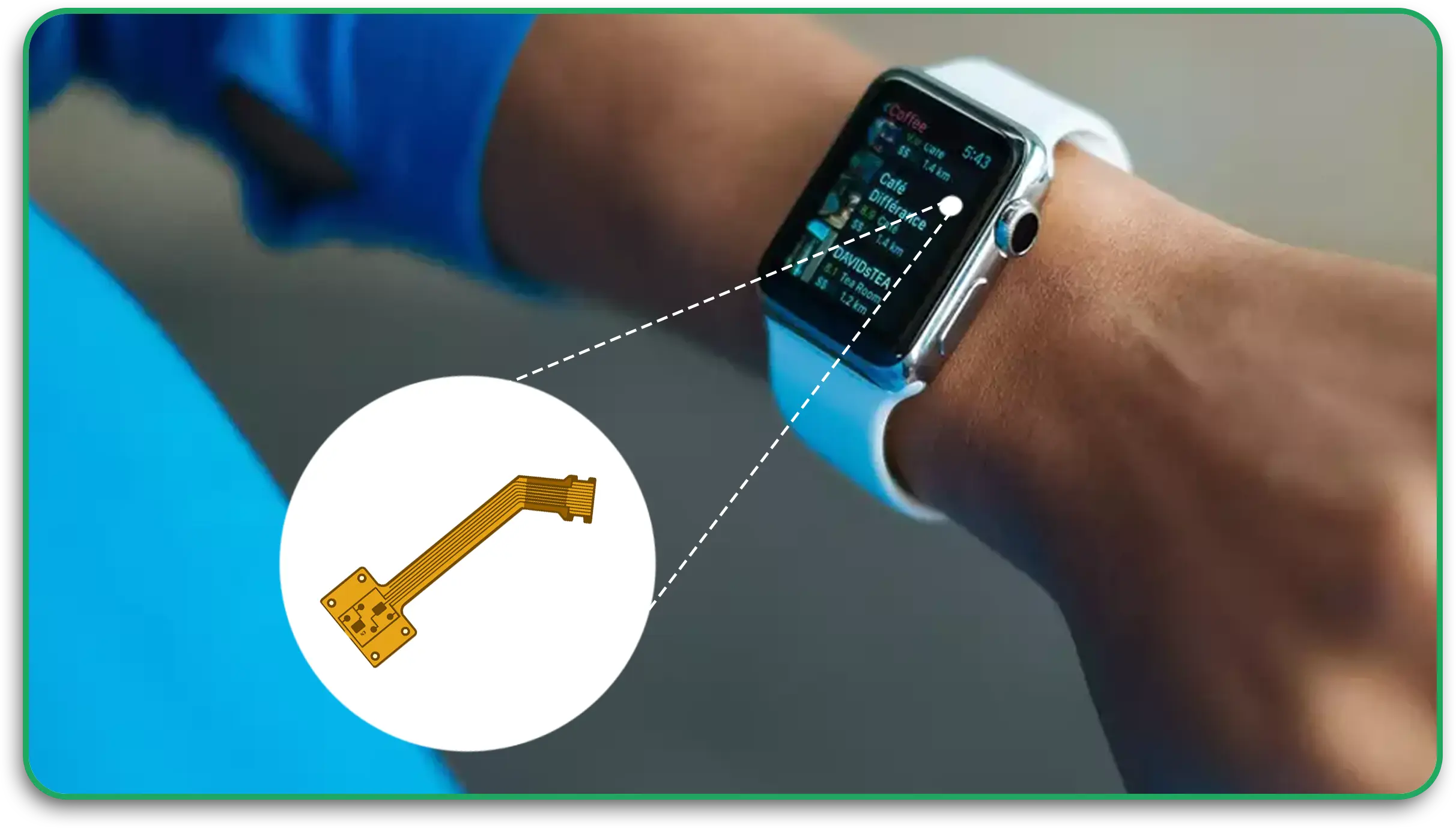
2. Smart Wearable Devices
FPCBs in smartwatches can be used because of their advanced ergonomic features.
3. Televisions with Curved Screens.
FPCBs are less fragile and the increase in display FPCBs allows for more broad usage in modern televisions.
4. Screens in Automobiles
The interface used in modern cars, with clusters and infotainment systems made with flexible FPCBs, has created customer-integrated curved displays.
5. Medical Devices
Today’s medical monitoring devices can be made smaller and more portable, owing to lightweight flexible PCBs that can adapt to a variety of displays.
Advantages of Flexible PCBs for Display Applications
Integrating FPCBs into flexible displays has many benefits:
- More Productive: Allows for diversity in the shapes of devices.
- Increased Reliability: Endures bending and moisture.
- Lowered Difficulty for Assembly: Reduced use of connectors and interconnects lowers assembly time.
- Electrically Efficient: Shorter signal paths enhance electrical performance.
- Financially Convenient: Reduced material usage and compact designs lower production costs.
Challenges and Solutions
There is always a price to pay for certain benefits, in this case, the manufacturing process of FPCBs for flexible displays:
1. Material Handling
Challenge: The flexible substrates are easily breakable and unsightly to deal with.
Solution: Use of automation and specialized handling tools for effective placement.
2. Signal Integrity Issues
Challenge: Signal loss from older traces.
Solution: Careful design and impedance control can help reduce signal losses.
3. Heat Management
Challenge: Slender devices have less surface area to cool off.
Solution: Using thermal vias and heat-dissipating materials.
Expert Insights
FCBs, or Flexible Circuit Boards, are vital components in contemporary electronics systems. They are present in mobile phones, laptops, smartwatches, cameras, and even robotic arms. These circuit boards are especially beneficial in applications with constrained spaces where standard Printed Circuit Boards (PCBs) cannot be utilized.
In comparison to conventional PCBs, FCBs possess several advantages like increased reliability, decreased weight, and more space efficiency. Nevertheless, they come with certain challenges, particularly during the installation and repair procedures of a system. During installation, FCBs are stressfully bent at multiple points which is significantly more than rigid PCBs. This stress, which gets compounded due to the system’s repeated bending, eventually leads to breakage.
The complexity increases when it comes to FCBs because of their structure and the requirement to model both the installation and operational phases of the model. Thus, in this study, a methodology for modelling these phases was created using Ansys Mechanical. The simulation determined the stresses induced during both phases and assessed the fatigue life of the FCBs after the operational phase.
Two types of models were studied: a Rigid-Flex PCB, which consists of a flexible circuit between two rigid PCBs, and a Flex FCB cable with no rigid components. For both models, shell elements were used to mesh the thin FCB structures, which rotate and bend significantly and are therefore subjected to large loads.
Trace mapping streamlined the intricate geometry of vias, solder connections, wires, and other electronic CAD components. This technique modelled the geometry as dielectric layers and mapped the metal fraction onto these layers so that the effects of the traces were accurately modelled. The models were bent at an angle of 180 degrees in order to study the fatigue due to this bending load.
For the FCB cable, there was some additional stress analysis conducted during the installation phase, because the stresses developed at this stage do have an overall bearing on the fatigue life of the cable. Rigid surface bodies were utilized in the simulation to deform the FCB cable into its final installed position to model real-world conditions.
This research also performed a High-Performance Computing (HPC) scalability analysis to provide optimal simulation performance. This analysis, in turn, determined the appropriate division of the processor cores against the time necessary to reach an accepted solution. This made it possible to simulate the model faster and more efficiently.
This study enriches knowledge of FCBs’ behaviour during the installation process and operation. In addition, it serves as an accurate predictor of performance and fatigue life, enabling engineers to design more effective FCBs for different electronic purposes. By preemptively spotting certain failure modes, the methodology increases the reliability and lifespan of these important components.
Conclusion
Flexible Printed Circuit Boards (FPCBs) are changing the landscape of display technology, bringing advancements such as flexible smartphones, curved TVs, and other smart wearable devices. The fusion of flex and rigid PCB technologies allows manufacturers to satisfy the increasing market need for multifunctional electronic devices. Anticipating future trends within the industry, FPCBs will be the basis for advanced next-generation displays for many years to come.
PCB Runners is a leader and supplier of high-quality flex and rigid PCBs for various applications across several industries. With our experience and reputation, we provide dependable and affordable PCBs specifically designed to meet our customers’ needs.
Frequently Asked Questions
Q1: What are flexible PCBs used for?
A: Foldable smartphones, wearable devices, automotive displays, and medical devices all utilize flexible PCBs due to their lightweight nature and easy adaptability.
Q2: What materials are used in FPCBs?
A: Polyimide substrates, copper conductors, and protective solder masks are commonly used materials.
Q3: What is the difference between flex and rigid PCBs?
A: Flex PCBs are adaptable to bending and twisting, whereas rigid PCBs have no flexibility. Rigid-flex PCBs offer the best of both worlds.
Q4: What challenges are associated with FPCBs?
A: Advanced material handling, signal integrity concerns, and thermal control are the major challenges with FPCBs. However, advanced manufacturing techniques can solve these problems.
Q5: Why choose PCB Runners for flexible PCBs?
A: When it comes to flex and rigid PCBs, PCB Runners has unmatched industry experience, top-tier materials, and specific peripheral solutions.

