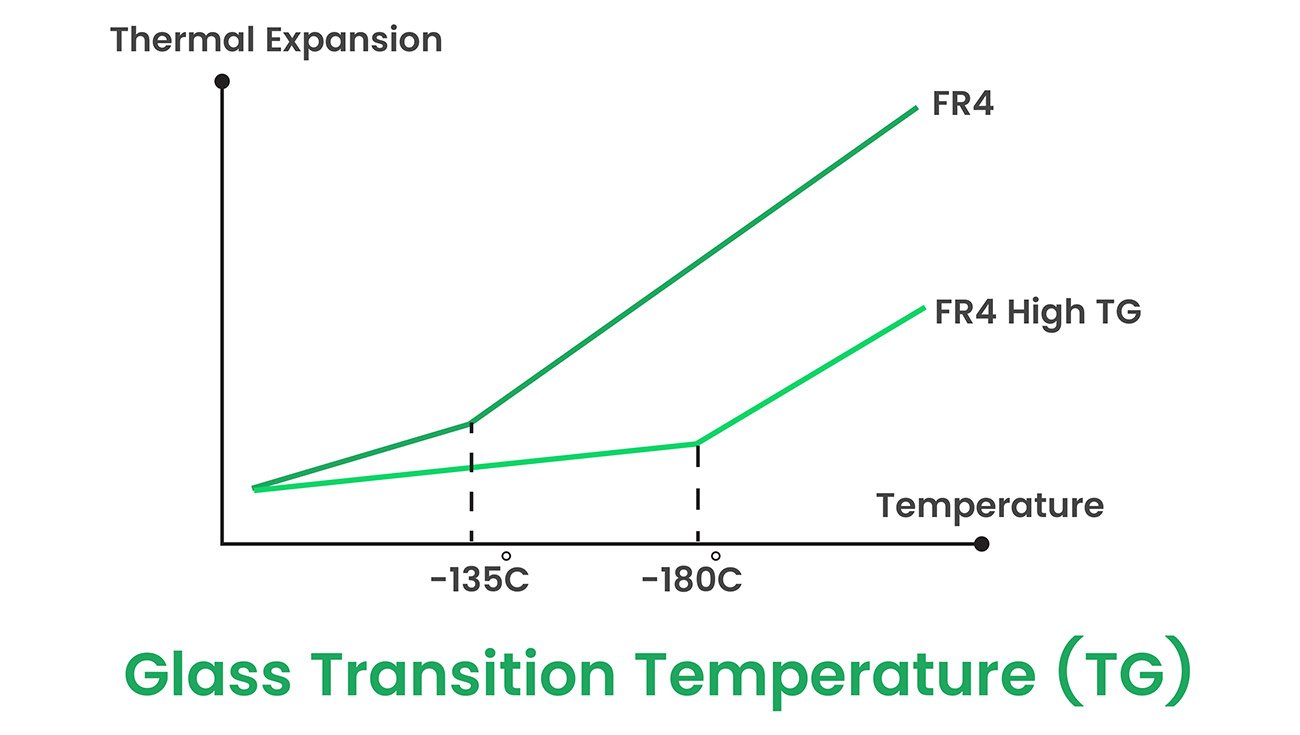
Our High Tg PCB material is much superior to that available in the market. Printed circuit boards made with this material can go through multiple thermal excursions without damage-six solder tests at 288 degrees each. We have optimized the material for superior drilling performance-high aspect ratio holes with up to 10 mil dia. The unique resin chemistry of this material offers CAF resistance along with long-term reliability, even for boards built with small feature designs. Even with regular fabrication techniques, this material allows improved productivity because of its fast cure capability.
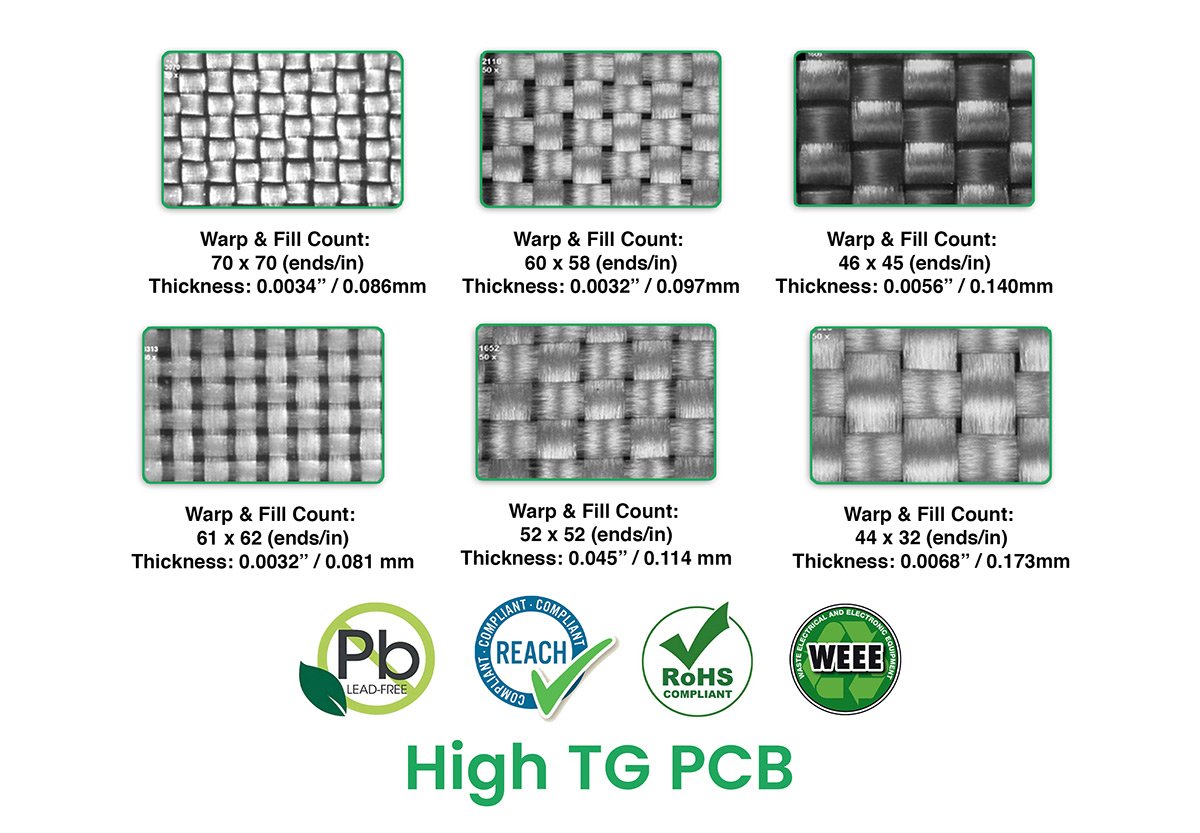
We also supply RoHS-compliant PCBs with Lead-free surface finishes such as:
- ENTEK / OSP (Organic Solder Preservative)
- Immersion Gold (IAu)
- Immersion Silver (IAg)
- Lead-Free Solder
- Immersion Tin (ISn)
and many others.
As our products comply with RoHS or the directive for Restriction of Hazardous Substances, we limit the use of substances such as:
- Polybrominated Biphenyl Ethers (PBBE) or PBDE
- Polybrominated Biphenyls (PBB)
- Mercury (Hg)
- Lead (Pb)
- Hexa-valent Chromium or Cr(VI)
- Cadmium (Cd)
For more details and quotations, please visit our website PCB Runner, email us, or call us over phone.

