Objective
If you design electronics in Europe, you often work with tight timelines, strict compliance requirements, and rapidly changing parts. In that setting, being able to recognise pc board components quickly is not a “nice to have.” It helps you debug boards faster, review layouts with confidence, and avoid costly mistakes during production. This blog explains PCB component identification in a clear, simple way, using practical examples. You will learn what to look for on the board, how markings work, and how to confirm a part when it is not obvious.
Many engineers also refer to practical build guides from PCB Runner when they want a clear, manufacturing-aware view of component recognition.
Key Takeaways
- Accurate recognition of pc board components reduces debugging time and rework.
- Knowing reference designators and package cues speeds PCB component identification.
- Many common PCB components look similar, so polarity and orientation checks matter.
- Europe-specific compliance (CE, RoHS, REACH) affects part selection and documentation.
- A simple process using BOM, datasheets, and basic tests helps confirm unknown parts.
Introduction to PCB Component Identification
Why Accurate Component Recognition Matters in Modern Electronics
Modern boards are dense. Parts are tiny. Labels are short. That makes PCB board component identification more important than ever. When you can recognise pc board components correctly, you can confirm design intent, spot assembly errors, and troubleshoot failures faster.
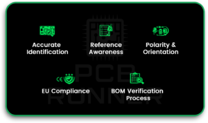
Accurate identification supports:
- faster prototype bring-up
- fewer polarity mistakes
- better repair and rework decisions
- cleaner communication between design and manufacturing teams
Common Challenges Faced by Designers and Engineers
Even experienced engineers can get confused, especially with common PCB components that share similar shapes.
Typical challenges include:
- unclear top markings on small SMD parts
- parts placed close together, hiding labels
- similar packages for different functions
- mixed vendors with varying styles of marking
Importance of Regional Standards and Compliance in Europe
In Europe, compliance is not optional. Rules like CE, RoHS, and REACH can impact which parts you can use and how you document them. Good PCB board component identification includes knowing what the part is and whether it meets compliance and traceability needs.
Overview of Printed Circuit Board Components
Active vs Passive Components Explained
A simple way to classify PCB components is into active and passive components.
- Passive components do not “add” energy. They shape signals and store or resist energy.
- Examples: resistors, capacitors, inductors.
- Active components control current or amplify signals.
- Examples: diodes, transistors, ICs.
This split helps you narrow down what a part might be based on its role in the circuit.
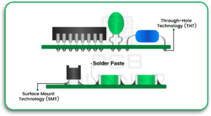
Surface Mount vs Through-Hole Components
You will also see components grouped by how they mount to the board.
- Surface-mount (SMD) parts sit on pads and are soldered to the surface.
- Through-hole parts have leads that pass through holes and are soldered on the other side.
Today, most pc board components are SMD because SMD saves space and supports automation.
Standard PCB Reference Designators and Markings
Reference designators are printed on the board silkscreen. They guide PCB board component identification by indicating the component type and category.
Common examples:
- R = resistor
- C = capacitor
- L = inductor
- D = diode / LED
- Q = transistor / MOSFET
- U = IC (chips, regulators, controllers)
- J / P = connectors
If you have a schematic or BOM, these designators help you match the physical board to the design.
Common Passive Components Found on PCBs
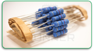
Resistors and Resistor Networks
Resistors are among the most common PCB components. SMD resistors are usually small rectangles with no readable markings, especially at small sizes.
How to recognise:
- simple rectangular body
- two pads, one at each end
- designator usually “R” on silkscreen
Resistor networks may look like a small IC package with multiple pins. They are used when several resistors are required in a single compact part.
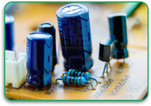
Capacitors Across Different Dielectric Types
Capacitors are also very common. They can look like resistors, but are often slightly thicker or a different colour.
You may see:
- ceramic capacitors (MLCC): small blocks, usually light coloured
- electrolytic capacitors: larger, can-shaped, with polarity marks
- tantalum capacitors: often moulded, polarity marked
Polarity matters for electrolytic and tantalum types. That is a common area for errors in PCB component identification.
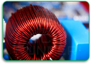
Inductors, Ferrite Beads, and Filters
Inductors vary widely. Some look like small blocks. Some look like coiled wire parts. Ferrite beads can look like resistors but are used for noise control.
Quick cues:
- Inductors are often larger in power circuits
- Ferrite beads often sit near connectors or power rails
- designator often “L” or sometimes “FB” on schematics
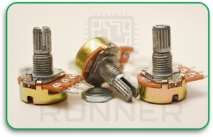
Potentiometers and Variable Components
Potentiometers are adjustable resistors. They are often used for calibration, tuning, or manual control.
How to spot:
- a small knob, screw slot, or adjustable top
- three pins (often)
- used near analogue input sections or control areas
Key Active Components in Modern PCB Designs
Diodes, LEDs, and Rectifiers
Diodes allow current in one direction. LEDs are diodes that emit light. Rectifiers are diodes used in power conversion.
How to identify:
- diode symbol reference designator “D”
- polarity marking, such as a stripe or dot
- LEDs are often clear or coloured with a lens
Polarity is critical. A reversed diode can cause power problems or overheating.
Transistors and MOSFETs
Transistors and MOSFETs control current and switching. They are core pc board components in power supplies, motor control, and switching circuits.
Common signs:
- three pins (or more)
- packages like SOT-23, SOT-223, DPAK, or larger power packages
- placed near power paths or heat areas
Integrated Circuits and Microcontrollers
ICs are the “brains” and control blocks of a board. They come in many packages: QFN, QFP, SOIC, BGA, and more.
For pcb board components identification, check:
- the “U” designator on silkscreen
- the pin 1 marker (dot, notch, or chamfer)
- the top code and manufacturer marking
Voltage Regulators and Power Management ICs
Regulators convert voltage levels and stabilise power rails. They are common near power input and near sensitive chips.
Clues include:
- placement near input connectors
- nearby capacitors and inductors
- larger copper areas for heat spreading
When reviewing a board, recognising these common PCB components helps you quickly follow the power path.
Connectors, Switches, and Electromechanical Parts
Board-to-Board and Cable Connectors
Connectors often have clear shapes and mechanical features. They also tend to sit on board edges.
Look for:
- locking tabs or latches
- pin arrays
- designators like J or P
Relays, Switches, and Push Buttons
Relays are larger and often box-shaped. Switches can be small tactile parts or larger mechanical sliders.
Relays are common in:
- mains switching
- high-current isolation
- industrial control boards
Sensors, Modules, and Communication Interfaces
Sensors can look like small ICs but are placed in function-specific areas. RF modules may have shielding cans. Communication parts often sit near connectors and antenna traces.
PCB Component Packages and Footprints
Common SMD Package Types Used in Europe
Package recognition speeds up PCB board component identification.
Examples:
- 0402, 0603, 0805: small passives
- SOT-23: small transistors
- QFN/QFP: common IC packages
- BGA: high pin-count chips, often underfilled or hidden
Package Size Codes and Dimension Standards
Passive size codes describe body size, not function. A 0603 can be a resistor or a capacitor. So you must combine size with the designator and circuit context.
Thermal Pads, Pin Pitch, and Orientation Marks
Many ICs have thermal pads beneath them to dissipate heat. Orientation marks help avoid wrong placement.
Always confirm:
- pin 1 indicator
- polarity markings
- silkscreen alignment
European Standards and Compliance Requirements
CE Marking and Safety Regulations
CE is about safety and compliance. It often affects insulation distances, creepage, and component approvals.
RoHS and REACH Material Restrictions
RoHS limits hazardous substances. REACH controls chemicals in products. This is why material declarations and part traceability matter.
IPC and IEC Standards Relevant to PCB Design
IPC covers design and acceptability. IEC standards often apply to safety and certain application areas. Good documentation makes compliance easier.
Tools and Methods for Identifying PCB Components
Using Schematics, BOMs, and Datasheets
The fastest way to identify PCB components is to use the BOM and match the reference designators. If the BOM is missing, use the top markings and the package plus circuit location.
Visual Inspection and Marking Codes
Use:
- magnification
- good lighting
- marking code databases (when needed)
Also, check the board text. If you have access to PCB board material data in the documentation, it can help when tracing heat issues or high-voltage spacing.
Digital Component Libraries and CAD Software
CAD libraries store footprints and 3D models. They help prevent mix-ups when parts look similar.
Testing and Measurement Techniques
When markings are unclear, light testing helps. Methods include:
- continuity checks
- diode mode tests
- measuring resistance or capacitance
- testing electrical circuits carefully to confirm function
If you are unsure, test out of the circuit when possible, because parallel paths can mislead readings.
Common Mistakes in PCB Component Recognition
Misreading Package Codes or Polarity
Top codes are short and can be confusing. Polarity marks can be tiny. Always double-check against the schematic.
Confusing Similar-Looking Components
Resistors and ferrite beads can look the same. Small capacitors can look like resistors, too. Context and designators matter.
Ignoring Regional Compliance Requirements
A part can be electrically correct but still not usable due to compliance or traceability rules.
Best Practices for European Electronics Designers
Standardised Documentation and Labelling
Clear silkscreen, consistent designators, and a clean BOM reduce confusion during reviews and repairs.
Component Traceability and Supply Chain Control
Counterfeit risk exists. Traceability helps. Work with approved distributors and keep part history.
A practical note: when you move from prototype to volume, aligning with a reliable pcb board manufacturer helps reduce variation and rework.
Designing for Reliability, Safety, and Certification
Keep margins for heat, voltage spacing, and assembly. If you are building products in Europe, certification needs should shape design decisions early.
If your team uses external help, such as PCB design services UK, make sure the handoff includes clear footprints, polarity notes, and compliance targets.
Did You Know?
- Many SMD passives have no markings at all, so designers rely on location and designators for identification.
- Some IC top codes are not unique, which is why BOM and schematic matching is safer than guessing.
- A polarity mistake on a diode or capacitor can cause failure even if the rest of the circuit is correct.
Frequently Asked Questions About PCB Components
How can I quickly identify an unknown PCB component?
Start with the reference designator, then check the package shape, nearby parts, and the schematic if available. Use only basic measurements after a visual review.
What standards must PCB components meet in Europe?
Most products must follow CE requirements. Materials often need RoHS and REACH compliance. IPC and IEC standards may apply based on product type.
How do SMD markings differ between manufacturers?
Many use different top-code systems. Some code is reused across parts. That is why datasheets and BOM links are important.
Which tools help automate component identification?
CAD libraries, BOM tools, and marking databases help. Visual inspection tools and microscopes also speed up checks.
How can designers avoid counterfeit components?
Buy from trusted channels, keep traceability records, and compare parts against known-good samples when possible.
Conclusion: Improving Accuracy in PCB Component Recognition
Recognising PCB components is a skill that saves time and prevents costly mistakes. The best results come from combining designators, package cues, documentation, and basic measurement methods.
In Europe, component identification also connects to compliance and traceability. When documentation is clear and processes are consistent, both debugging and certification become easier.
Many engineers sharpen these practices by learning from manufacturing-aware resources such as PCB Runner, especially as they move designs toward production and review.

