In the world of modern electronics, precision defines success. Even the smallest component misalignment can compromise the performance of an entire circuit. Among the most overlooked details in board design and manufacturing is Pin 1 orientation, a crucial factor in ensuring accurate assembly, reliable operation, and long-term functionality.
If you’ve ever been involved in Design for Assembly (DFA), PCB assembly services, you’ll know that the correct identification and placement of Pin 1 is key to avoiding costly errors. Whether it’s a microcontroller, connector, or integrated circuit, a single misplaced component can lead to short circuits, reversed connections, or complete board failure.
Let’s explore why Pin 1 orientation is so important, how it affects the quality of your build, and the best practices that help manufacturers get it right every time.
At PCB Runner, we emphasize the importance of correct orientation at every stage from design through turnkey PCB assembly ensuring your products meet performance and quality standards.
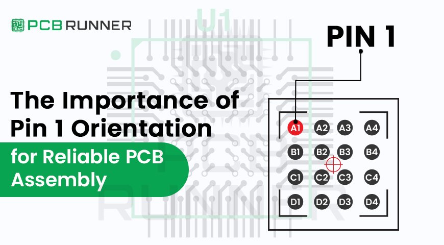
What is Pin 1 Orientation and Why is it Important?
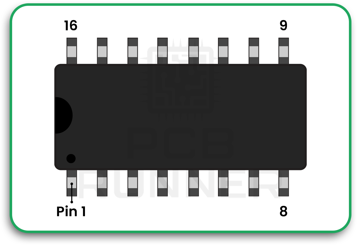
Every component on a printed circuit board (PCB) has a specific way it must be placed. The “Pin 1” mark identifies the starting point of a component’s connection pattern. On ICs, connectors, or headers, this mark tells the assembler which way to align the part on the board.
When the Pin 1 orientation is incorrect, signals travel through unintended paths, leading to functional issues and potential component damage. In surface-mount and through-hole components alike, incorrect placement can also make soldering inconsistent and cause rework delays.
In short, clear marking and consistent handling of Pin 1 orientation are the foundation of reliable turnkey PCB assembly operations.
The Role of Design in Correct Orientation
The first step in ensuring proper Pin 1 placement begins during the PCB design stage. Engineers must clearly define orientation indicators within the layout software. This often includes silkscreen markings, pin numbering, or specific pad shapes that visually guide assemblers.
CAD libraries should include standardised component footprints that clearly denote Pin 1. It’s good practice for design engineers to maintain consistent labelling conventions across all components, as it minimises the risk of confusion later during manufacturing or inspection.
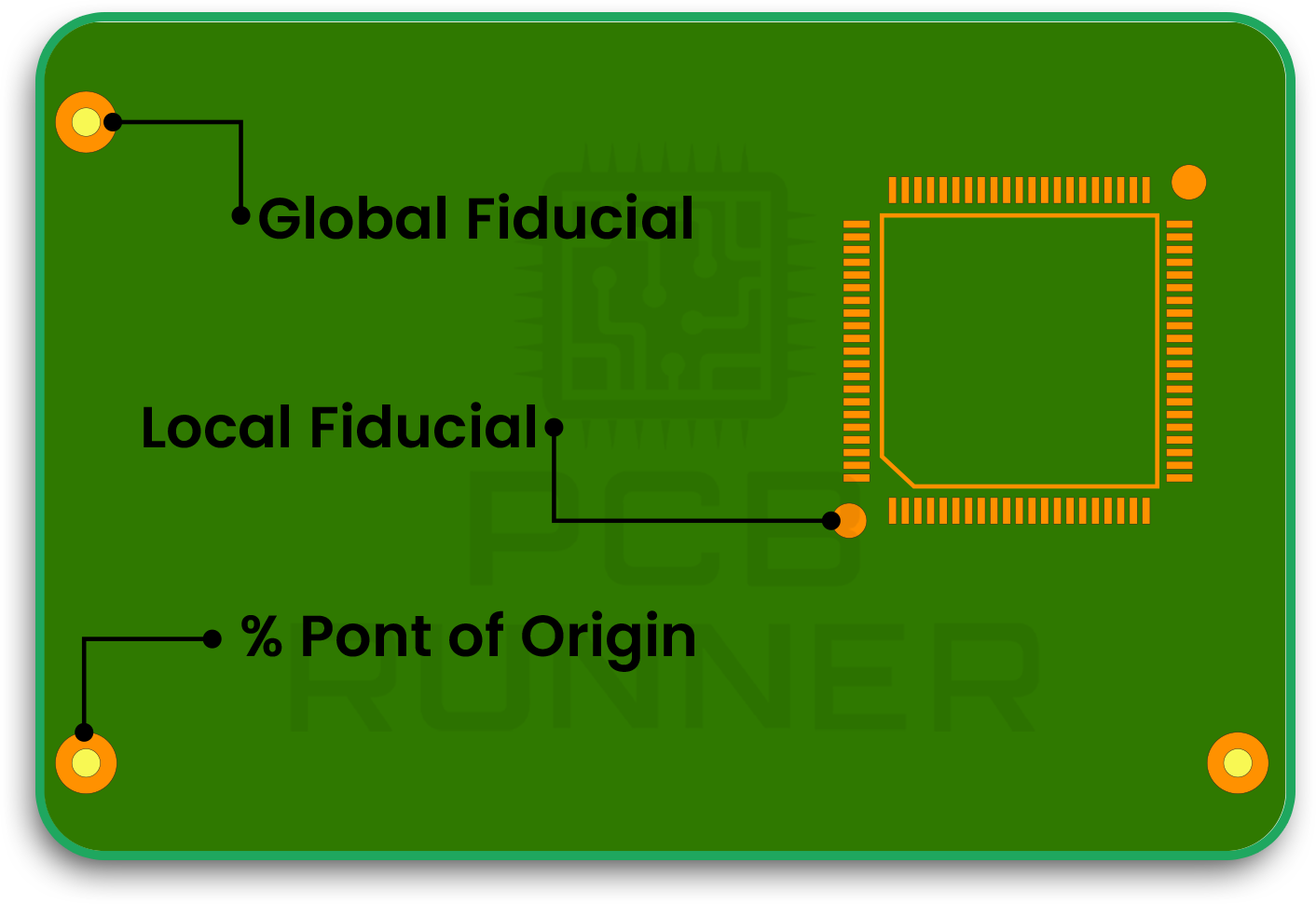
Some additional design practices that improve orientation reliability include:
- Adding fiducial marks for camera alignment in automated system
- Including Pin 1 notches or dots in the silkscreen.

- Cross-verifying footprints before finalising Gerber files.

Even with automation and inspection tools, clarity at the design level remains critical for preventing assembly errors.
How Pin 1 Orientation Impacts Automated Assembly
In automated PCB assembly tips, proper orientation is vital to smooth production flow. Pick-and-place machines depend on optical recognition to position components precisely on the board. If the Pin 1 mark is unclear or inconsistent, the equipment may rotate or misplace the part.
When this happens, production lines must be stopped to correct the issue, increasing downtime and rework costs. Repeated mistakes can also reduce overall yield and delay project timelines.
Additionally, when it comes to surface-mount technology guide practices, solder paste application and reflow temperature profiles rely heavily on correct part orientation. Incorrect alignment can cause bridges, tombstoning, or cold joints, all of which compromise the reliability of the finished product.
PCB Runner ensures reliable results with advanced quality checks at every stage contact our sales engineers at sales@pcbrunner.com.
Common Mistakes That Lead to Orientation Errors
Despite clear industry standards, Pin 1 orientation errors still occur for several reasons:
- Inconsistent footprint libraries where the Pin 1 indicator is missing or mislabelled.
- Ambiguous silkscreen symbols that confuse manual assemblers.
- Incorrect rotation settings in pick-and-place programming.
- Human oversight during visual inspection or manual placement.
Simple preventive measures such as design audits, automated optical inspection (AOI), and staff training can help avoid these common pitfalls.
Best Practices for Reliable Pin 1 Orientation
Ensuring correct Pin 1 alignment requires cooperation between design, manufacturing, and quality control teams. Here are some widely adopted practices:
- Use clear silkscreen markings: Every component footprint should visibly indicate Pin 1. Adding a small dot, notch, or arrow on the board helps both automated systems and human assemblers quickly identify orientation. Consistent markings across all boards also make inspection faster and reduce placement errors during production.
- Standardise component libraries: Maintain a unified design database across all projects. When every designer works from the same verified footprint library, inconsistencies in Pin 1 indication are eliminated. This approach improves communication between design and assembly teams while reducing time spent on rework or clarifications.
- Verify with visual inspection: Always double-check component placement before soldering. A quick inspection stage using AOI (Automated Optical Inspection) or manual review helps catch misaligned parts early. Detecting orientation errors before reflow saves costs, materials, and prevents functional issues in the final assembly.
- Cross-reference pick-and-place data: Ensure machine orientation data matches the design file. Verifying this alignment before the assembly run prevents misplacement of components during automated mounting. It’s also a good habit to review the rotation parameters defined in the CAD software and machine program for consistency.
- Train assembly staff: Clear communication between engineers and technicians prevents confusion. Regular training sessions on reading orientation marks and interpreting PCB layouts can significantly reduce assembly mistakes. When the whole team understands the importance of Pin 1 alignment, overall production reliability improves.
How PCB Runner Maintains Orientation Accuracy
Companies like PCB Runner integrate precision and process control into every step of the assembly workflow. From automated placement to AOI verification, each board passes through multiple quality checks that ensure components are oriented correctly before soldering.
Their experience in handling complex assemblies helps ensure that clients receive dependable results, especially when working with fine-pitch components or mixed-technology layouts. Consistency in Pin 1 orientation directly contributes to overall production efficiency and product reliability.
The Connection Between Pin 1 and Overall Board Performance
Although it may seem like a small design detail, the position of Pin 1 can influence overall board integrity and signal performance. Misalignment often results in reversed polarity or crossed signal paths that can lead to data errors or component failure.
In high-speed or high-density designs, where precise trace routing is essential, even a slight error in orientation can disrupt impedance control and introduce unwanted noise. Ensuring accuracy from the start prevents such performance degradation and extends product lifespan.
Conclusion: Getting the Details Right
In PCB assembly, reliability comes from paying attention to detail. The orientation of Pin 1 is one of those seemingly minor factors that can make or break the success of a design. Correct alignment ensures that signals flow as intended, components perform efficiently, and the finished board meets its expected lifespan.
PCB Runner maintains orientation accuracy to help manufacturers and engineers achieve reliable results. Whether you are working with complex prototypes or large-scale production, ensuring proper Pin 1 placement through trusted PCB assembly services and verified processes will always be a critical part of achieving consistency and quality in your builds.